Home / Writing / A fully reversible Polaroid Pathfinder 110a / 110b / 800 / 150 & Lomograflok conversion
Introduction
This is a project that started a quite while ago. I had found and purchased a Polaroid 110a with the original intention of converting it to shoot Instax wide. I ended up destroying three Instax Wide 300s before getting to a point where I successfully mounted a horribly fragile bodged back to the 110a, using some plywood and way too much Sugru. It was a difficult conversion that involved cutting away part of the 110a’s body (going through who knows how many Dremel metal cutting discs). I ended up with something that really took surprisingly good photos. Sure it spat out skew horizons, it was difficult to frame photos accurately, and it wasn’t pretty to look at, but it proved one thing: give Instax good glass and it sings.
And then Lomography surprised everyone with the Lomograflok. Of course I preordered one right after it was announced. Although the original intention of the back was to bring Instax to 4x5 cameras (and it does this very well), even before release the usual makers (like Ethan Moses and Max/SPRKPLG) spotted the potential of this device to be paired with good lenses to create a serious portable solution with incredible results.
So I got to work and ended up desiging a 3D-printable conversion that works really well, but unfortunately still requires that you cut into the camera body. Somewhere in the back of my mind I wasn’t happy with this at all. So I started tinkering once again. I played around with the infinity focus distance, and found that moving the film plane back another 4mm or so still made conversion possible. And here we are again. A fully reversible conversion with the only “damage” to the camera being two small rivets that get removed.
Before we start
A few caveats
Before we get stuck in, there are a couple of things you should know:
- Because of the 110b and Lomograflok’s geometry, and how this conversion was designed, your pictures will be “upside down”, with the wide part of the frame on the top (I quite like the different look it gives)
- Framing is slightly off, but you get to know by how much quite quickly
You will need
Tools:
- A drill with a small bit to drill out the infinity stop rivets
- A set of precision screwdrivers
- You might need a hammer to tap in the hinge pins
- A 3D printer if you intend to print the bracket, new infinity stop, grips, and the cold-shoe adapter yourself (optional)
Parts:
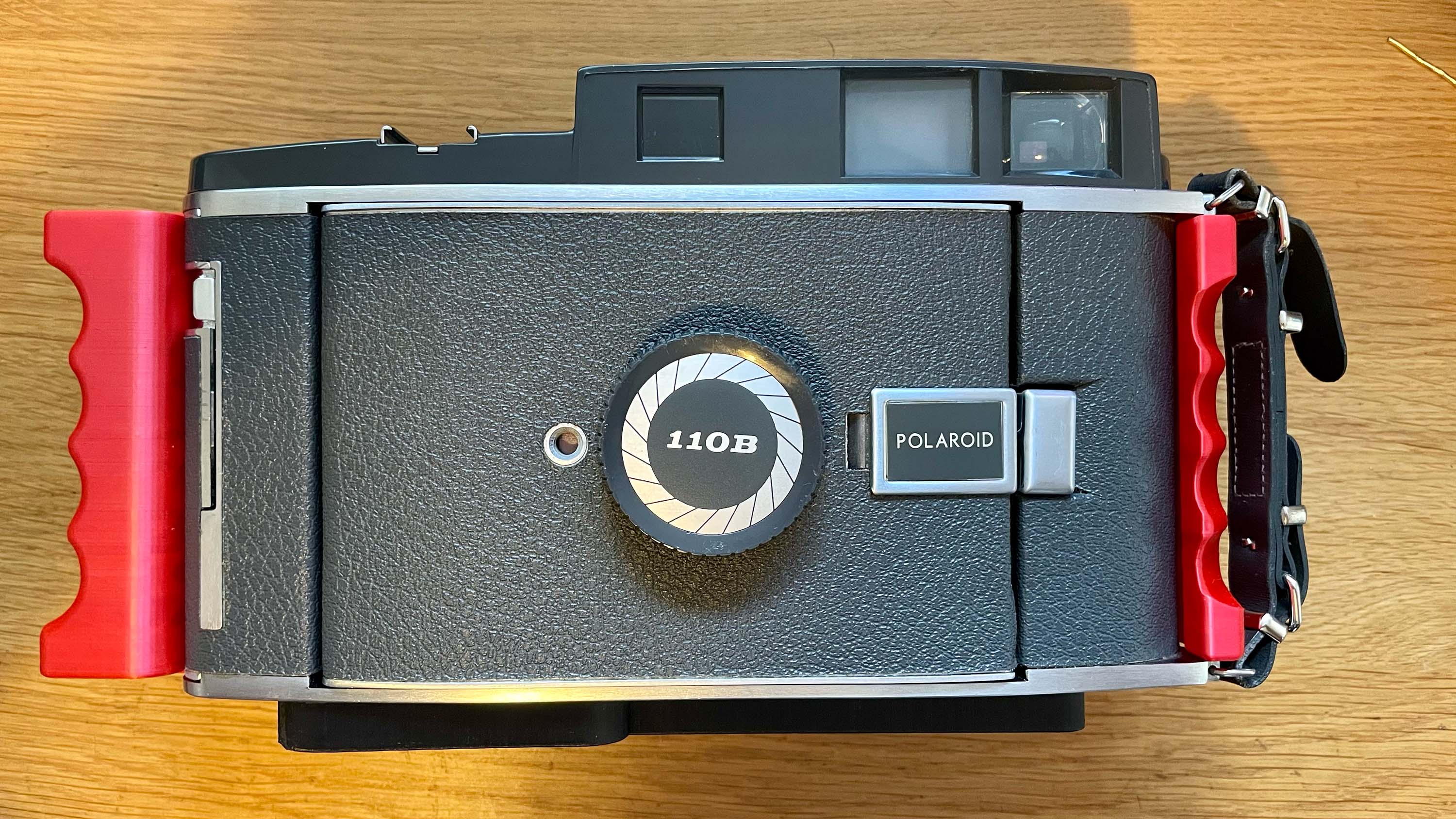
- A Polaroid Pathfinder 110b, 110a, or 800/150 (the bracket fits all these model without issues)
- A Lomofraflok Instax wide back
- Lomograflok / 110 mounting bracket (3D printed)
- Modified infinity stop (3D-printed)
- Left-hand grip (3D-printed, optional, make sure you print the right one for your specific model)
- Right-hand grip (3D-printed, optional, make sure you print the right one for your specific model)
- Double cold-shoe adapter (3D-printed, optional)
- Door pin and spring shim (3D-printed, only if you’re converting a 110a)
- A sheet of light-sealing foam to cut to size (I use 1.5mm thickness)
- 1/4-20 tripod screw with length 16mm (excluding head)
- 1/4-20 tripod screw with length 11mm (excluding head)
- 3/8-16 male to 1/4-20 thread apapter - Google for SmallRig 1610
- An empty Instax wide cartridge
- Either ground glass, a perspex sheet, or just the lid off a takeaway curry container cut to size (I used the lid approach)
The conversion
Step one: print your parts
This one’s optional, as you may opt to order these from a 3D printing company instead, but I think it’s pretty important that I at least provide the settings used to get results that I was happy with (after many tries).
Click here to download the necessary files from Printables, Thingiverse, or download them directly:
Disclaimer: I’m very confident about the parts needed for the 110s, but there are many cameras that Polaroid released where they mixed and matched bits, so the conversion should theoretically work with the 120, 150, 160, and 800/150 as well, but you might need to print out both versions of the grips and see which ones work for your camera.
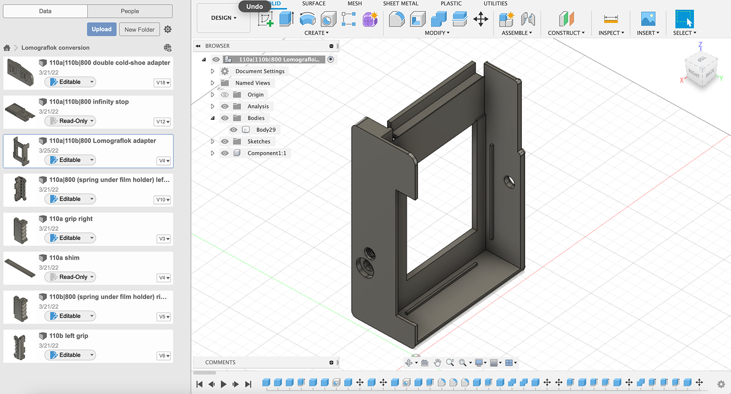
I used a Creality Ender 3 v2, which is an incredible machine for the price. Cura slicer was used to slice my STL files to G-code. All the models are in the recommended orientation for printing already. Your temperatures will vary depending on the material you choose to print with, but I think these settings will help you get results that are both pretty and strong (it takes forever to print, though, so tweak until it suits your needs):
- Layer height: 0.2mm (0.16mm for the grips makes it easier to thread the hinge pins)
- Wall thickness: 0.8mm
- Wall line count: 3
- Top/bottom thickness: 0.8mm
- Infill density: 20%
- Enable print cooling: Yes
- Fan speed: 100%
- Initial fan speed: 0%
- Regular fan speed at height: 0.8mm
- Generate support: Yes
- Support placement: Everywhere
- Support type: Line
- Support density: 15%
- Build plate adhesion type: Brim
I used a brand of filament from Amazon called “Eryone”, and decided on the matte black for the bracket, and red for the grips and inifinity stop. I set the hot-end to 205 degrees celsius, and my bed starts out at 65 for the initial layer, then eases down to 60 degrees celsius for the rest.
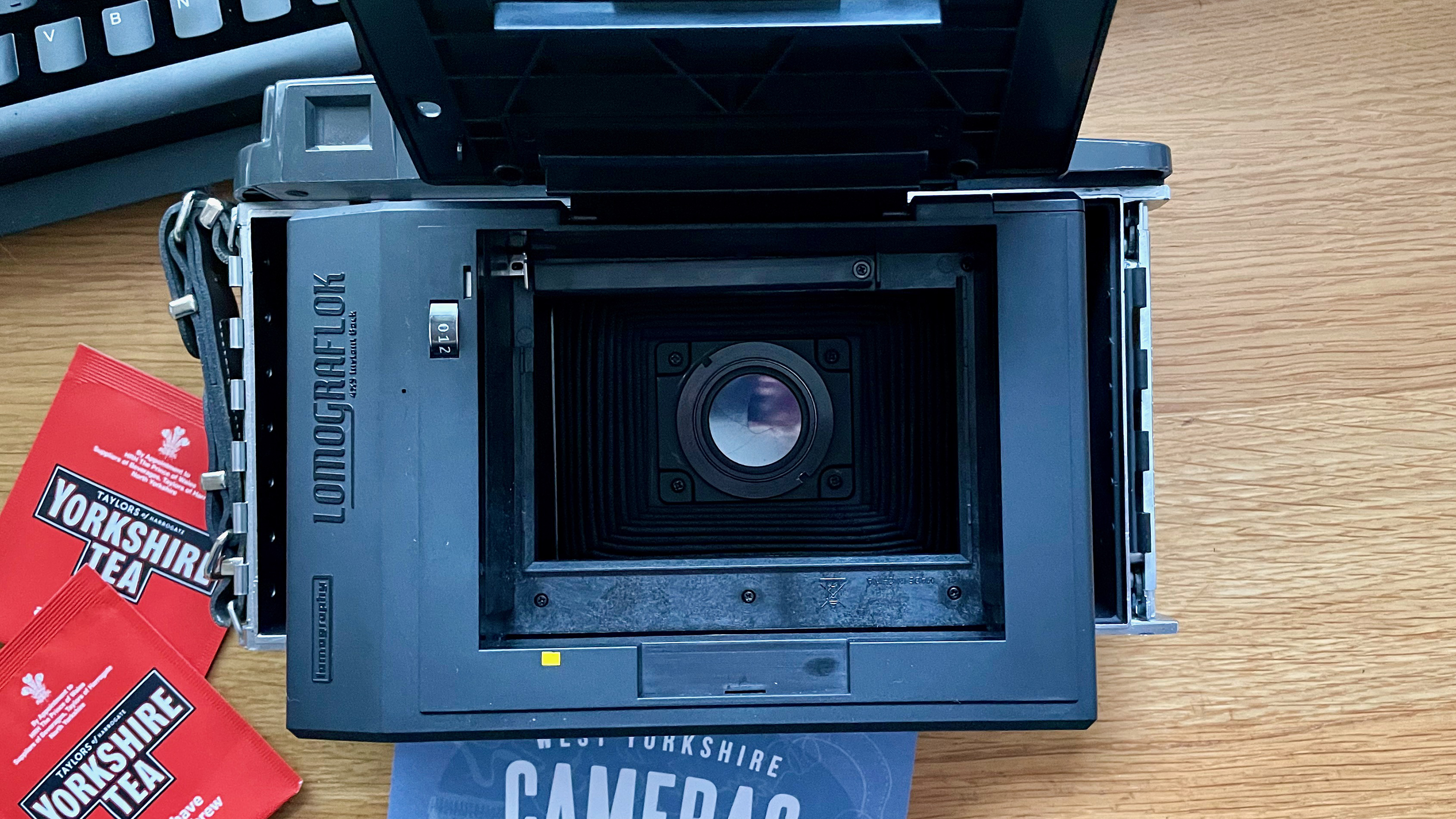
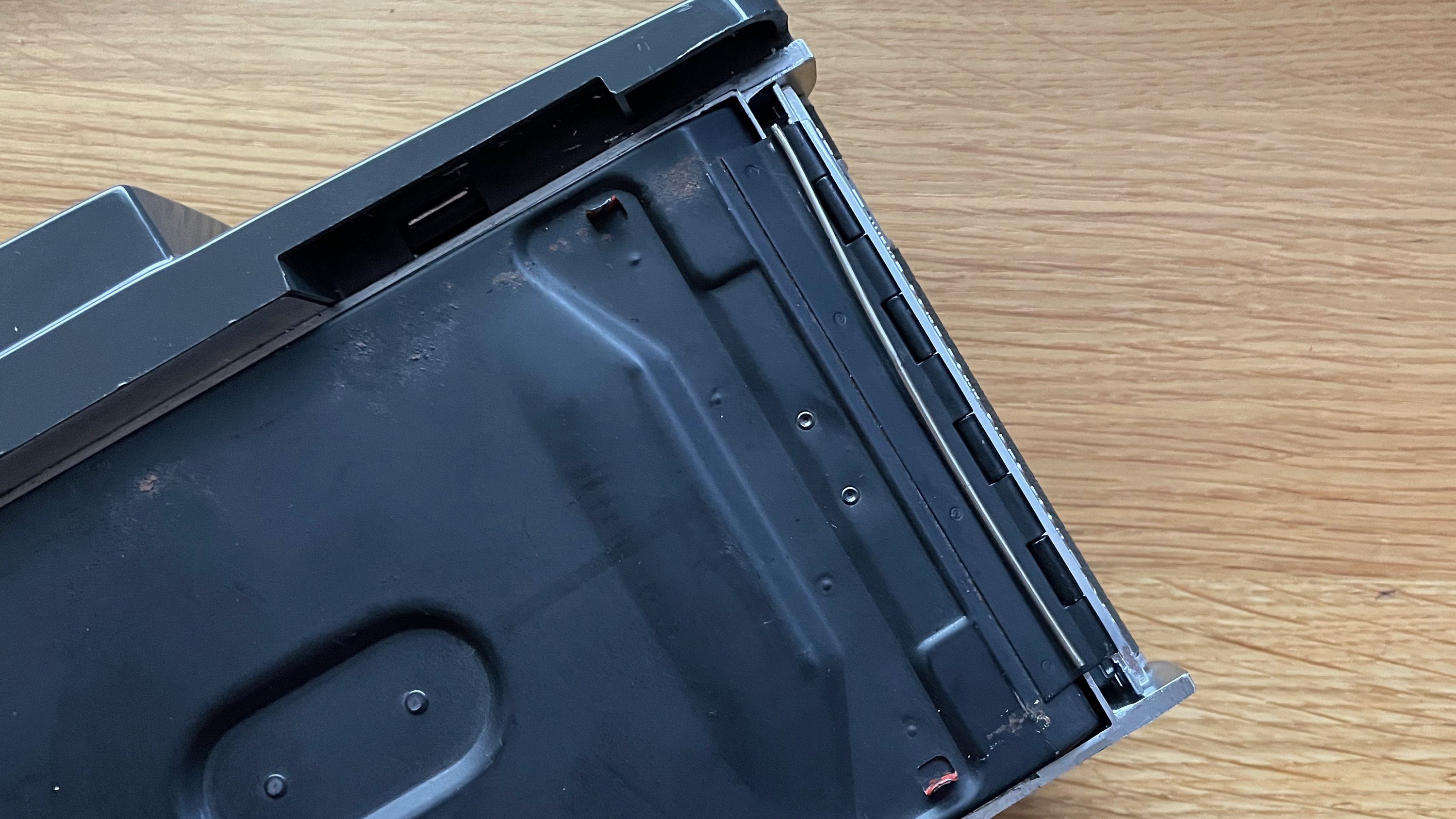
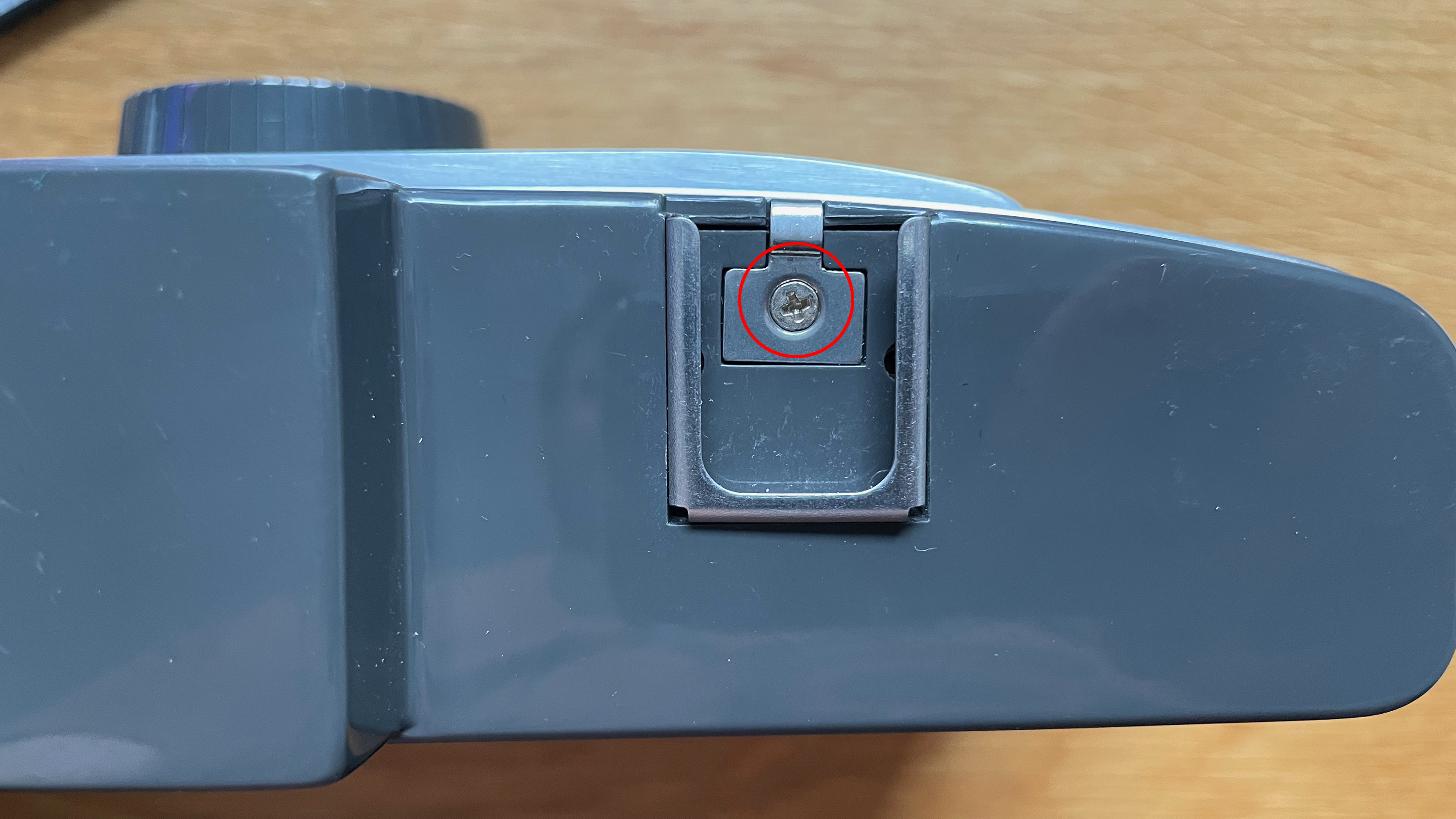
Step two: remove the back door(s) and film holder
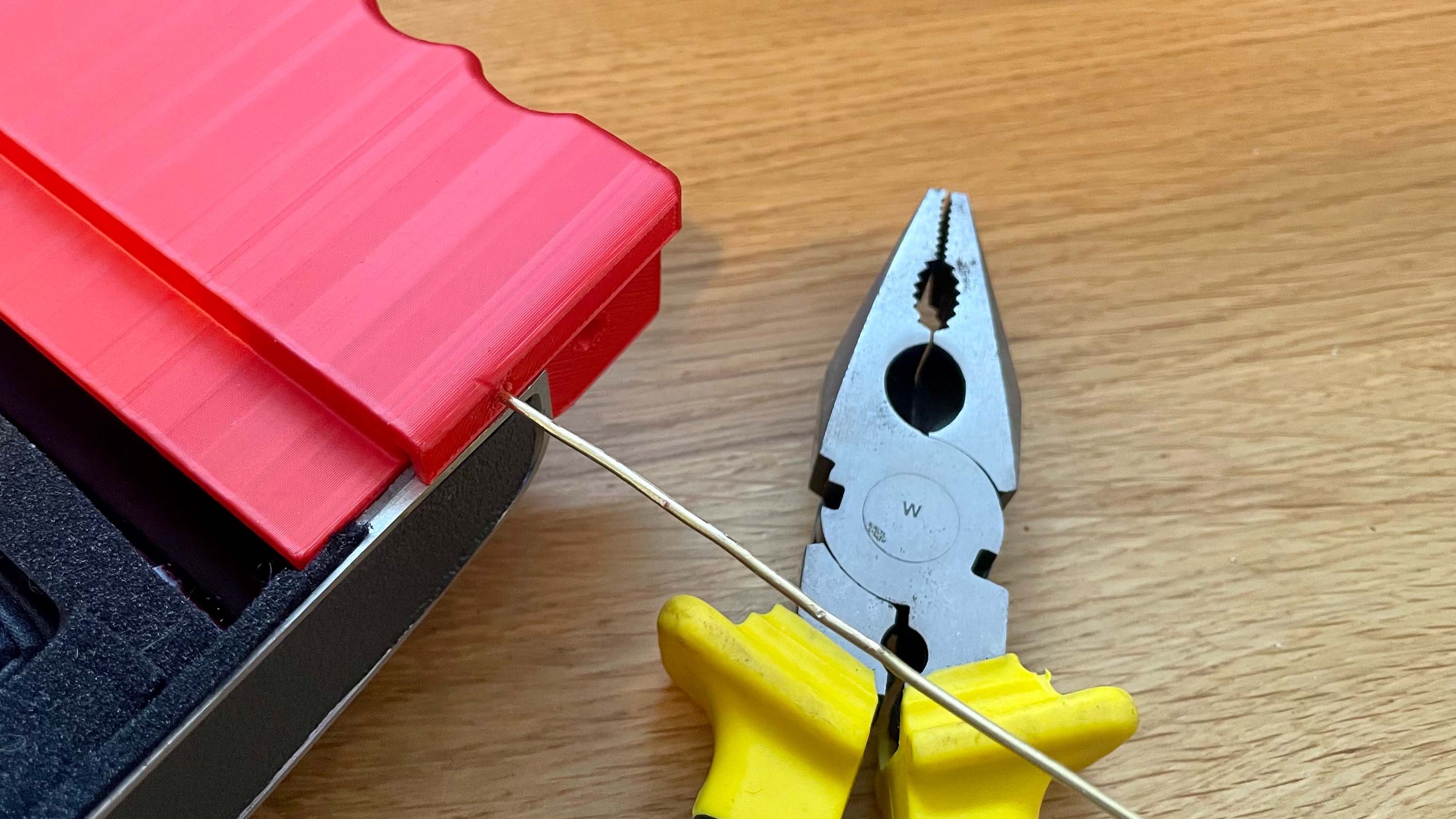
Both the rear door and inner door are held in place with a thin rod threaded through the hinge. Getting it out is as easy as poking the smallest screwdriver (or even better, a pick) that fits into the topmost hole of the hinge. If you’re lucky, you should just be able to push out the rod, grab it from the bottom with a pair of pliers, and pull it all the way out. If not, you’ll need to gently tap the top of your screwdriver (or pick) with a hammer until it peeks out. Do this with the rear door first (left hinge), then the inner door (right hinge), and set them aside (keep them if you ever want to restore the camera to its original state). Keep the rods, you’ll need both of them if you decide to use the grips.
If you have difficulty gettting to the pin on the right side hinger, it may be easier if you remove the top cover first, see instructions lower down.
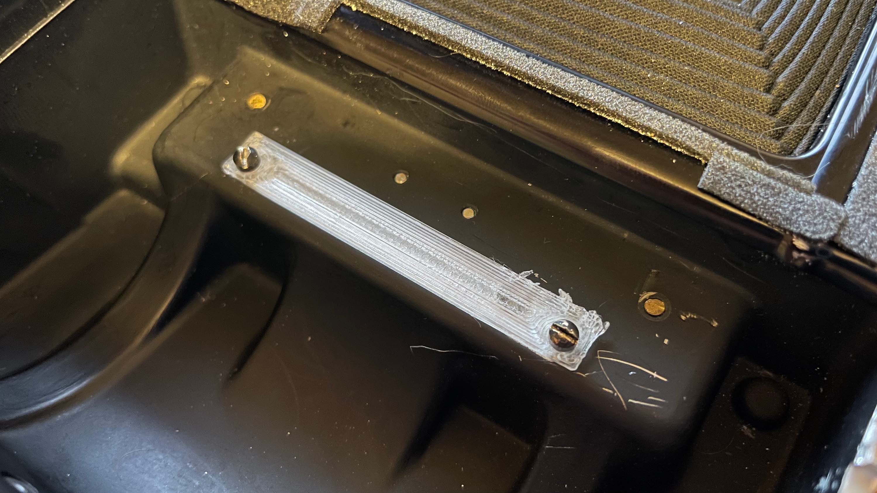
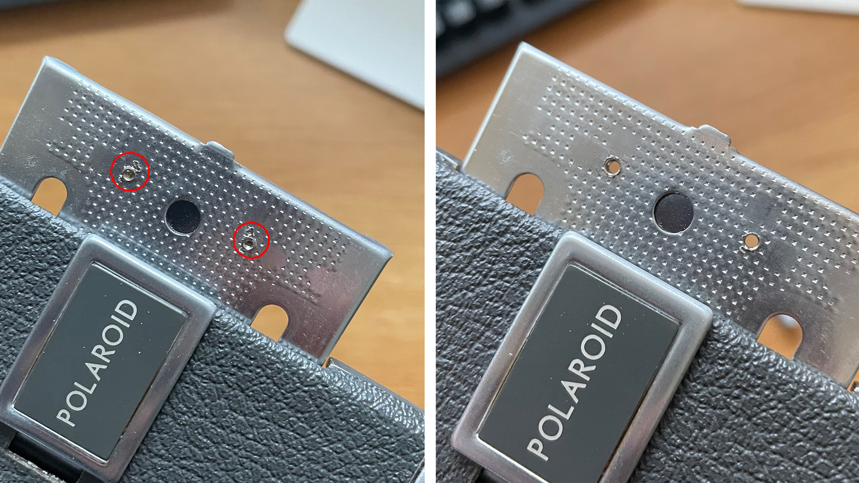
Next, inside the camera on the left is a piece of plastic that was used to hold the original Polaroid roll film. It has two small screws. Unscrew them, remove the plastic piece, and replace the screws for light-tightness (and aesthetics).
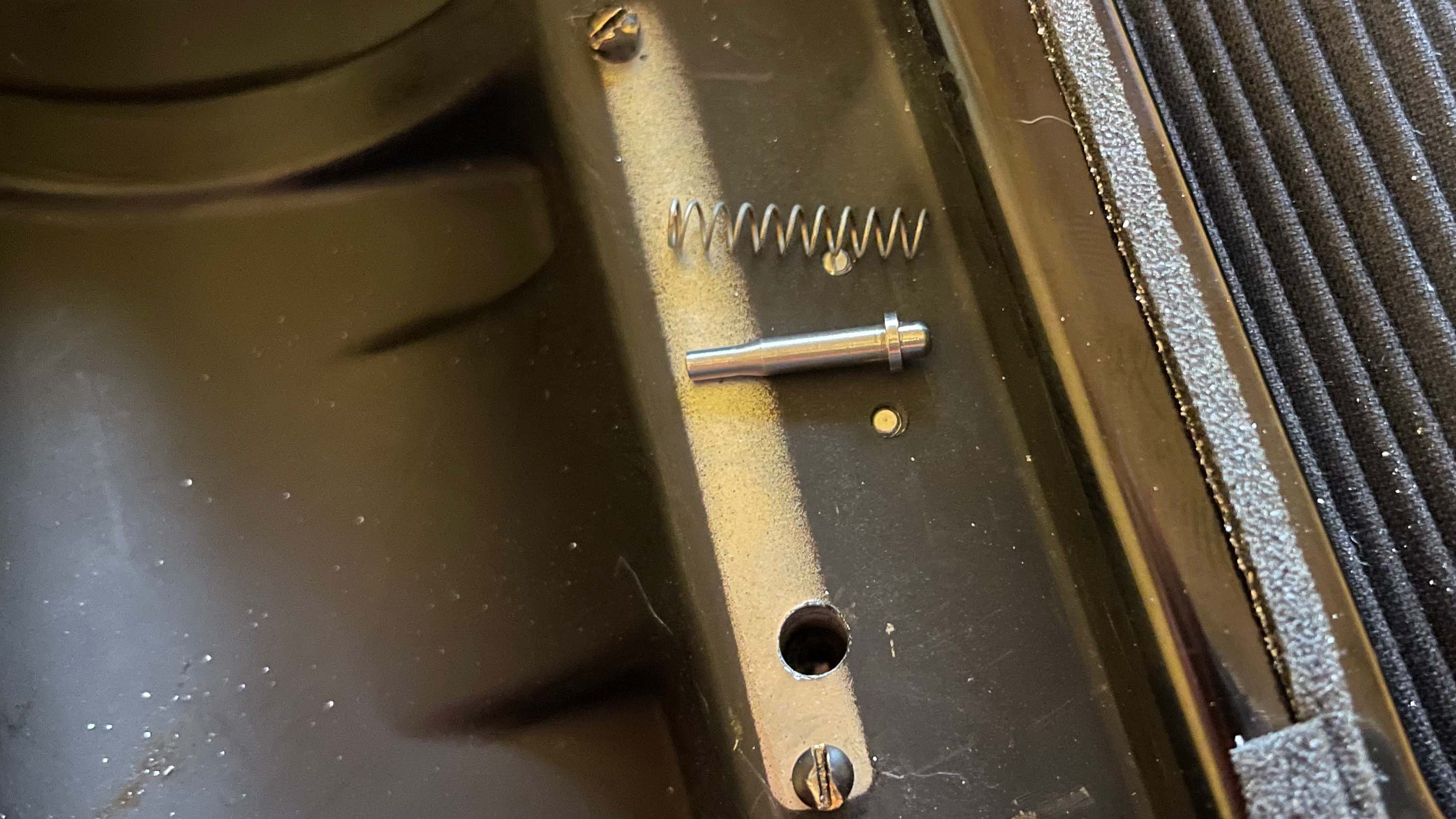
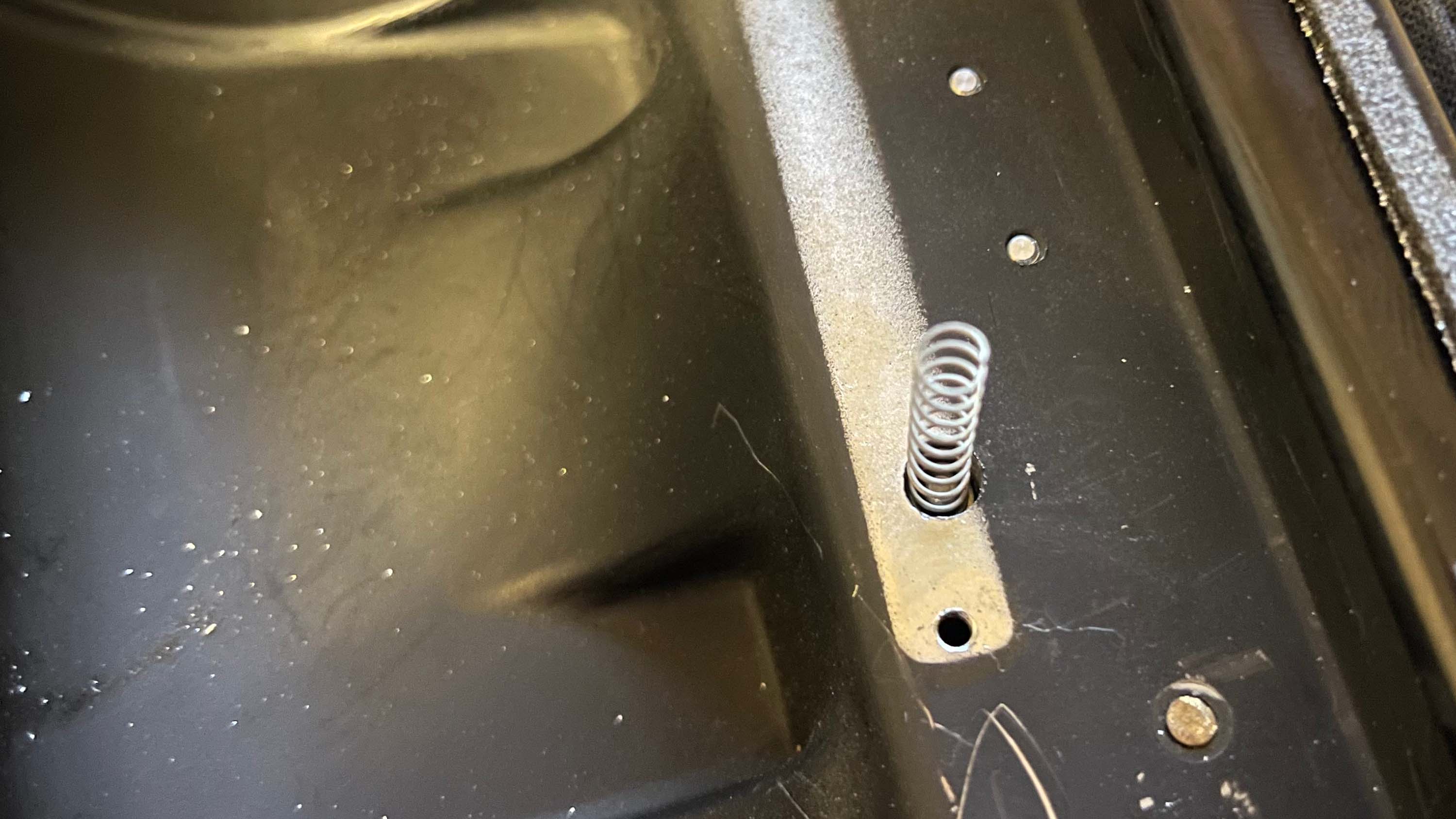
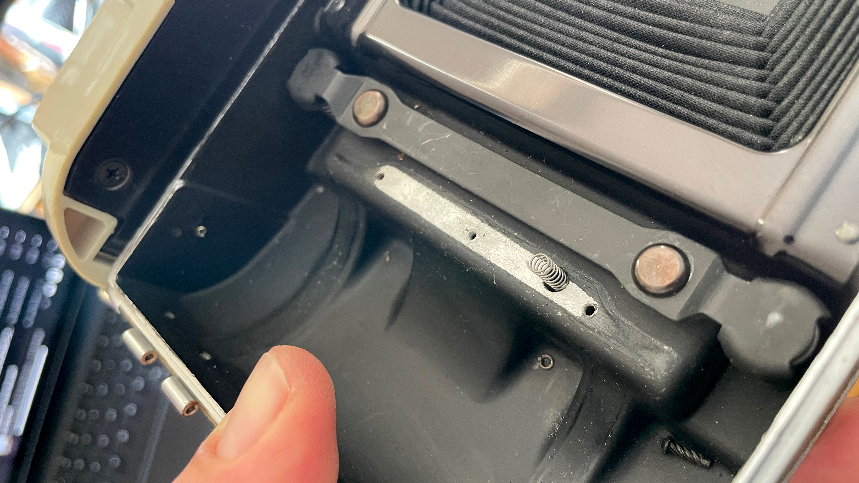
For the 110a the lens door pin and spring sits behind this plastic piece. Be careful when removing it as the spring will shoot out and be lost to time (if you do lose it, a ballpoint pen’s spring does the job). Once you’ve removed the plastic and collected the pin and spring, place them back into the hole carefully, and hold them in place by screwing the 3D-printed shim into the holes that were holding the plastic piece.
For the 800 I’ve seen two variants, one that looks like the 110b, where you can just remove the film holder with screws (and the door pin and spring are under a separate metal bar), and then there’s the version that has the door pin and spring under the film holder, and this film holder is riveted to the camera body. Unfortunately you need some force to get both the rivets and film holder out and will probably end up destroying it. After it’s out you can use the 110a 3D-printed shim and two screws to hold the pin and spring in place. It’s a faff, so when buying an 800, look closely at the photos and try to avoid those with this style of film holder.
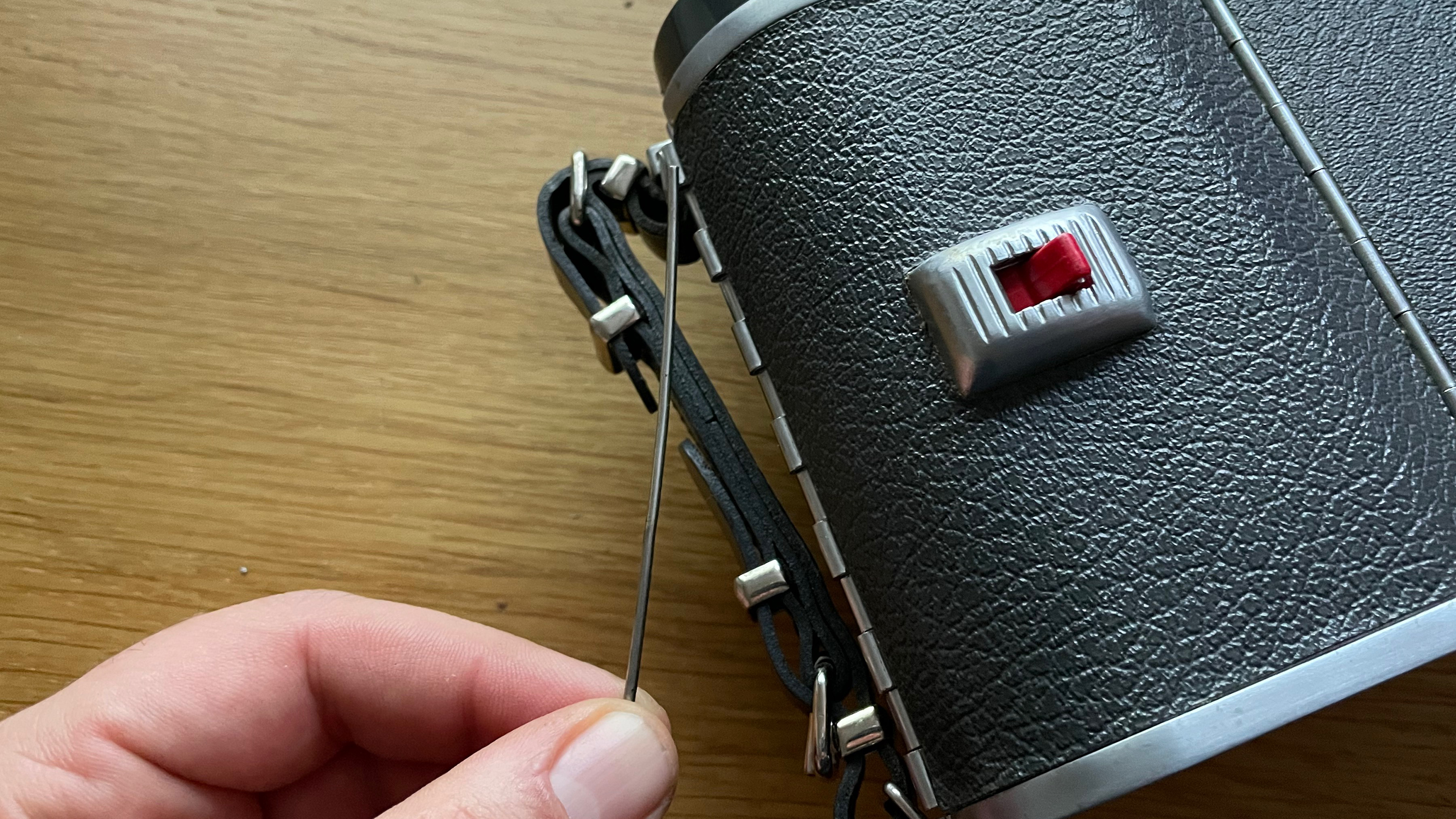
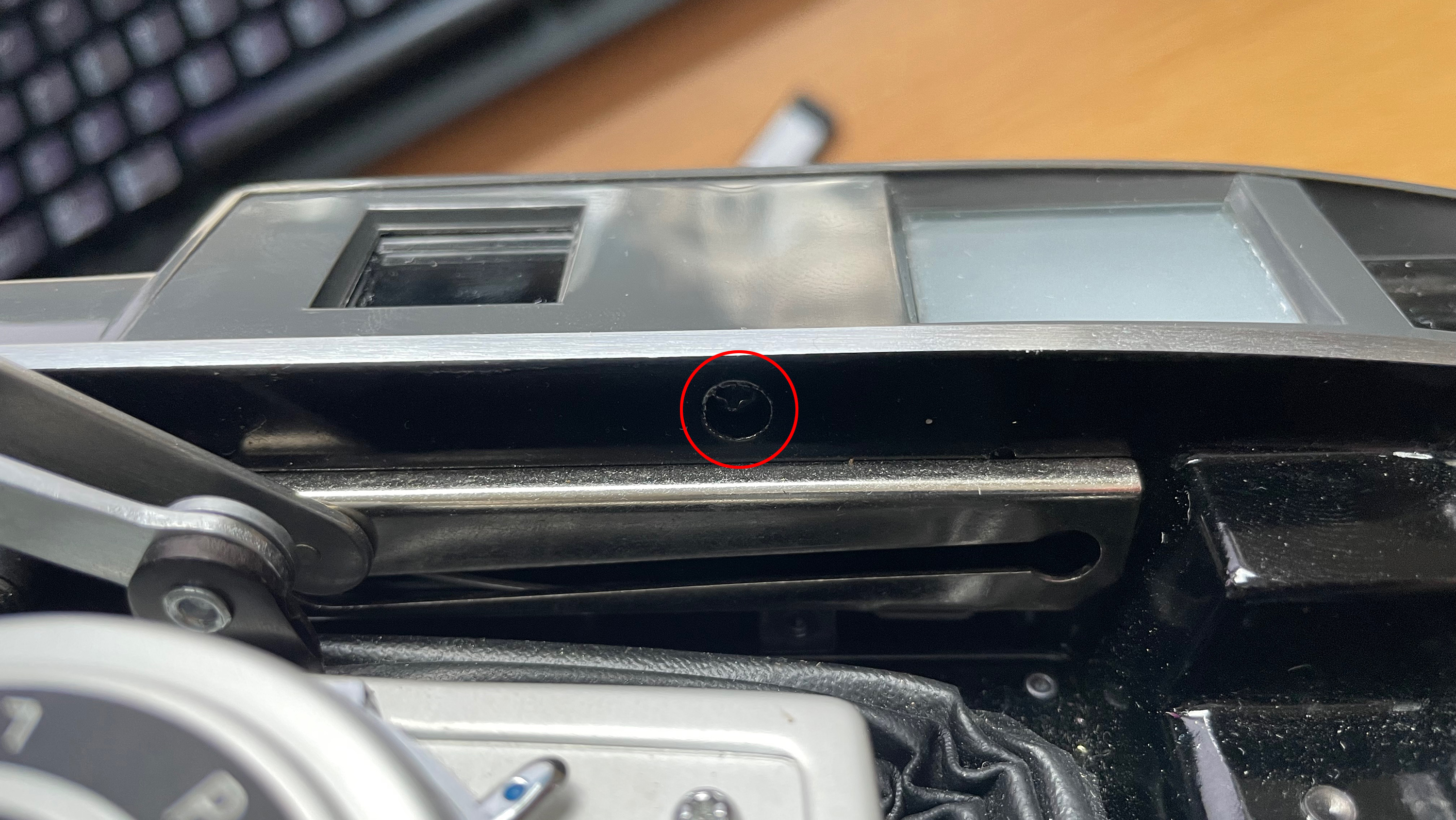
Step three: mount the new infinity stop
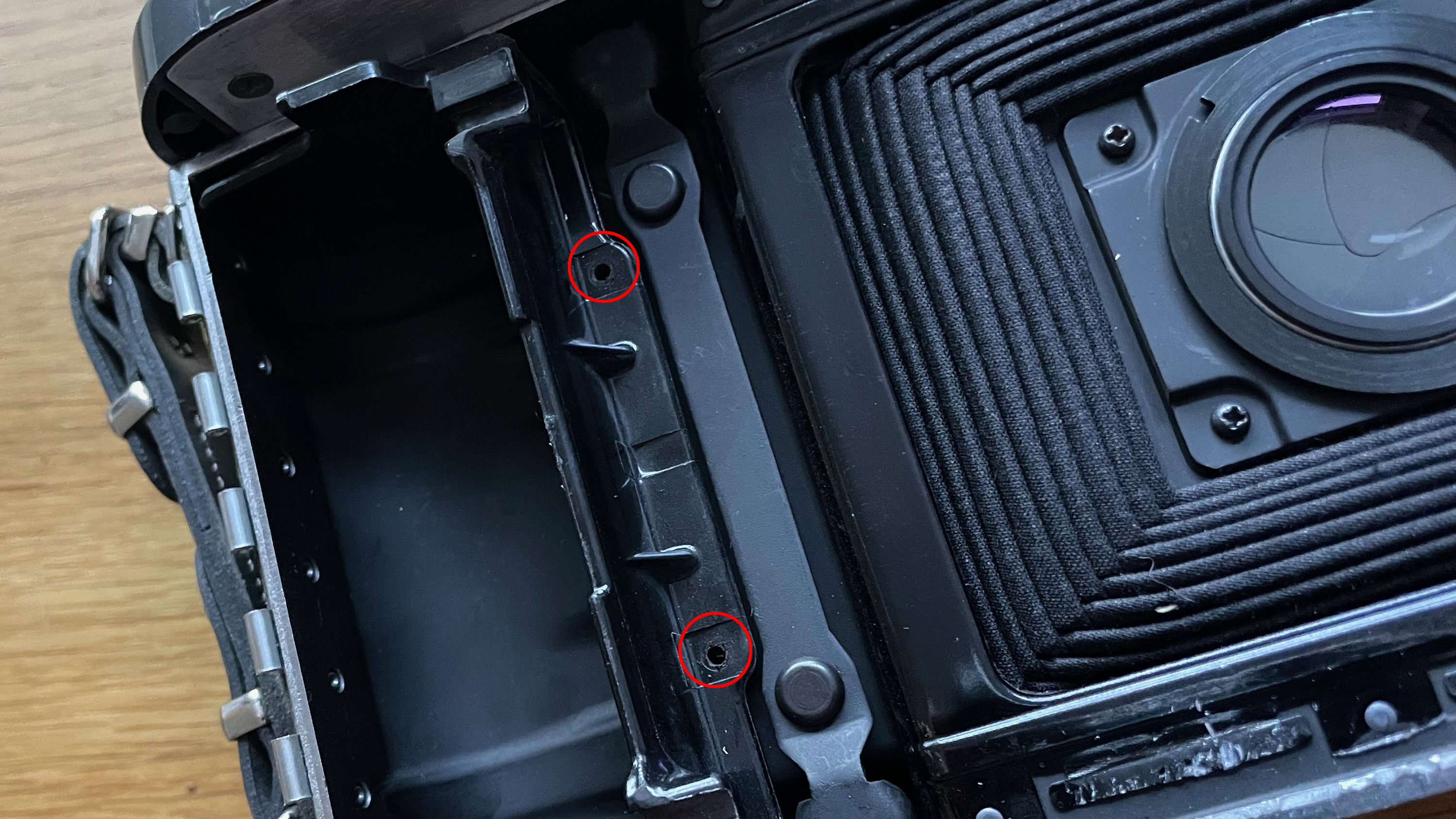
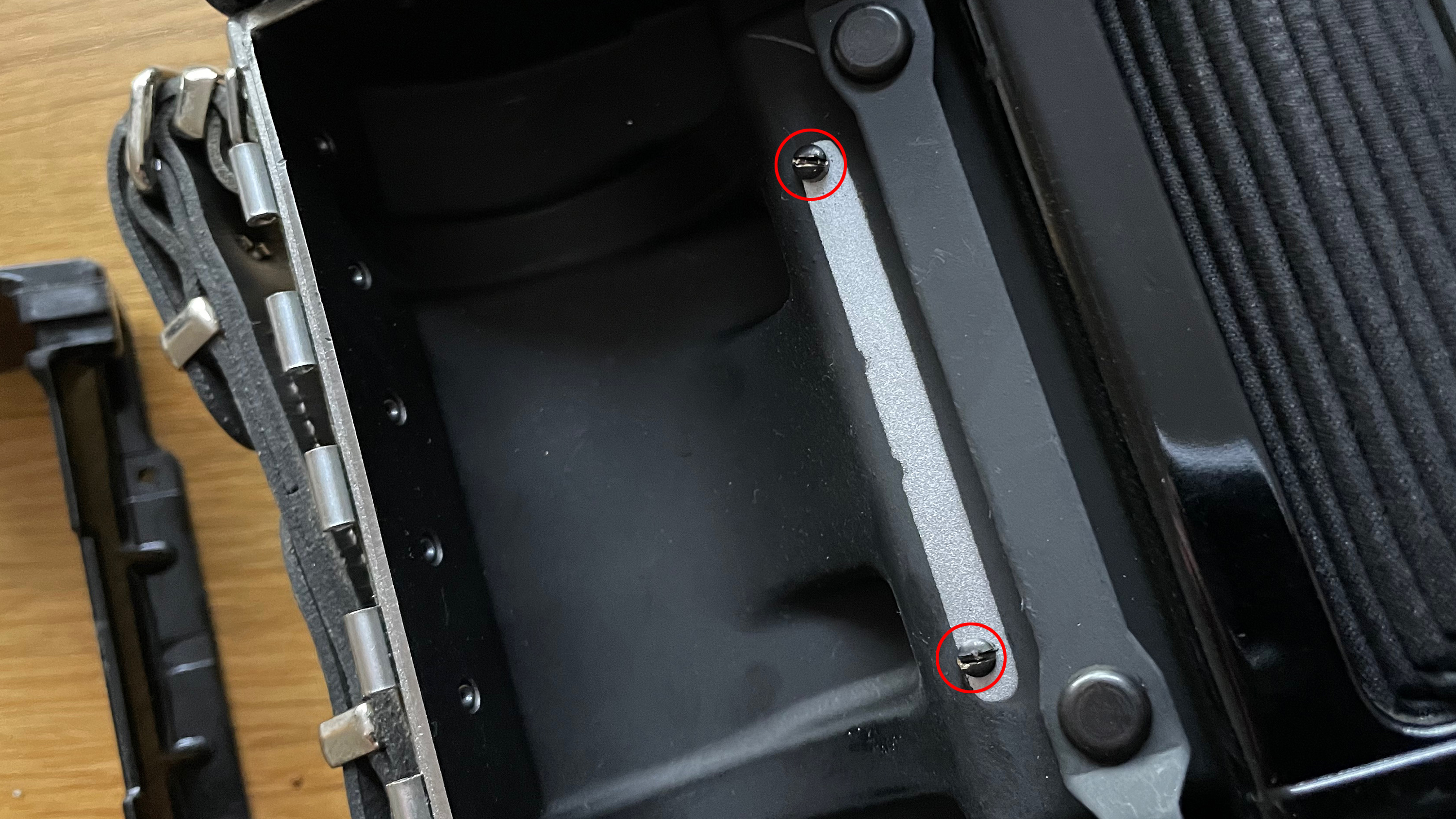
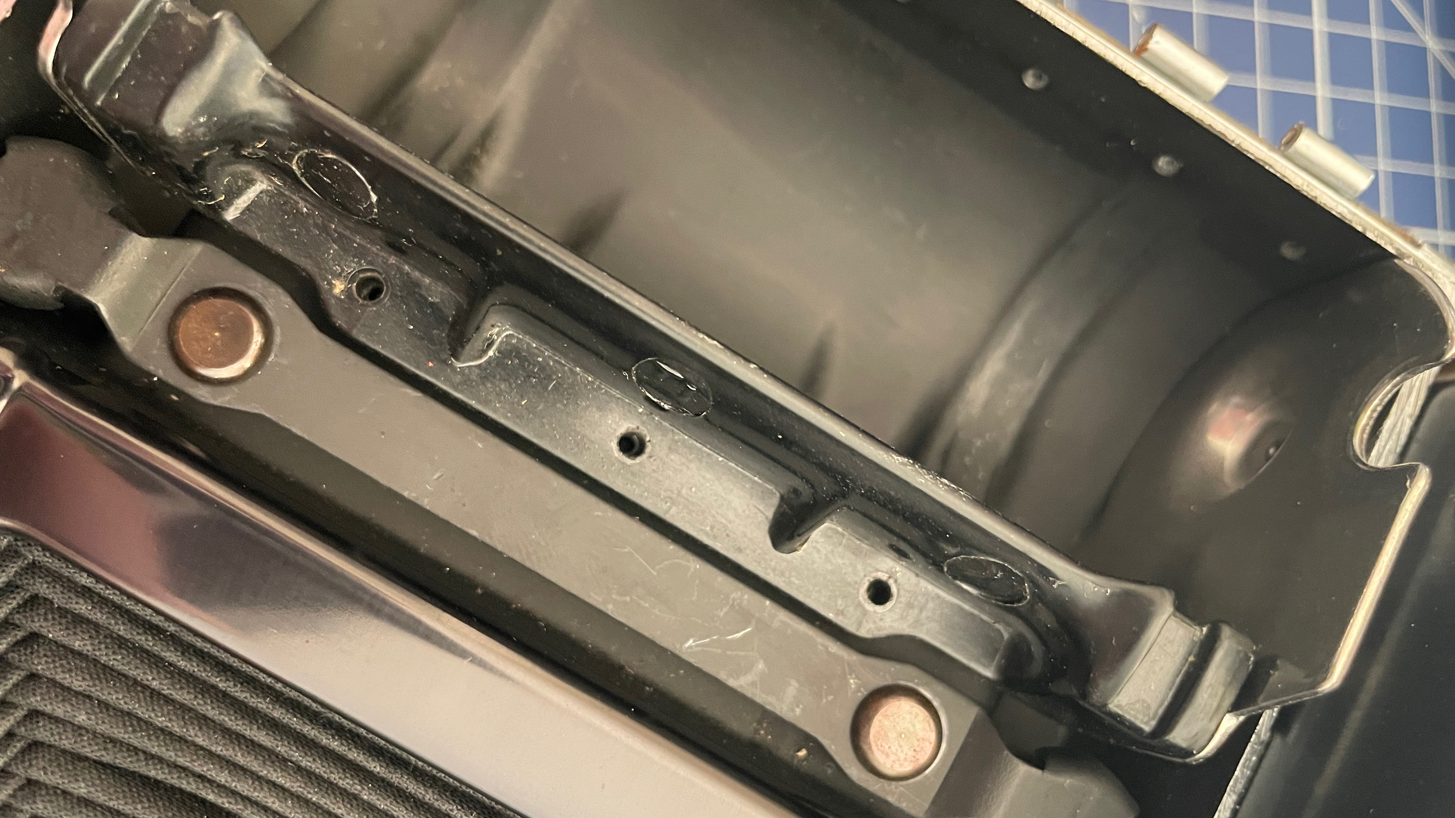
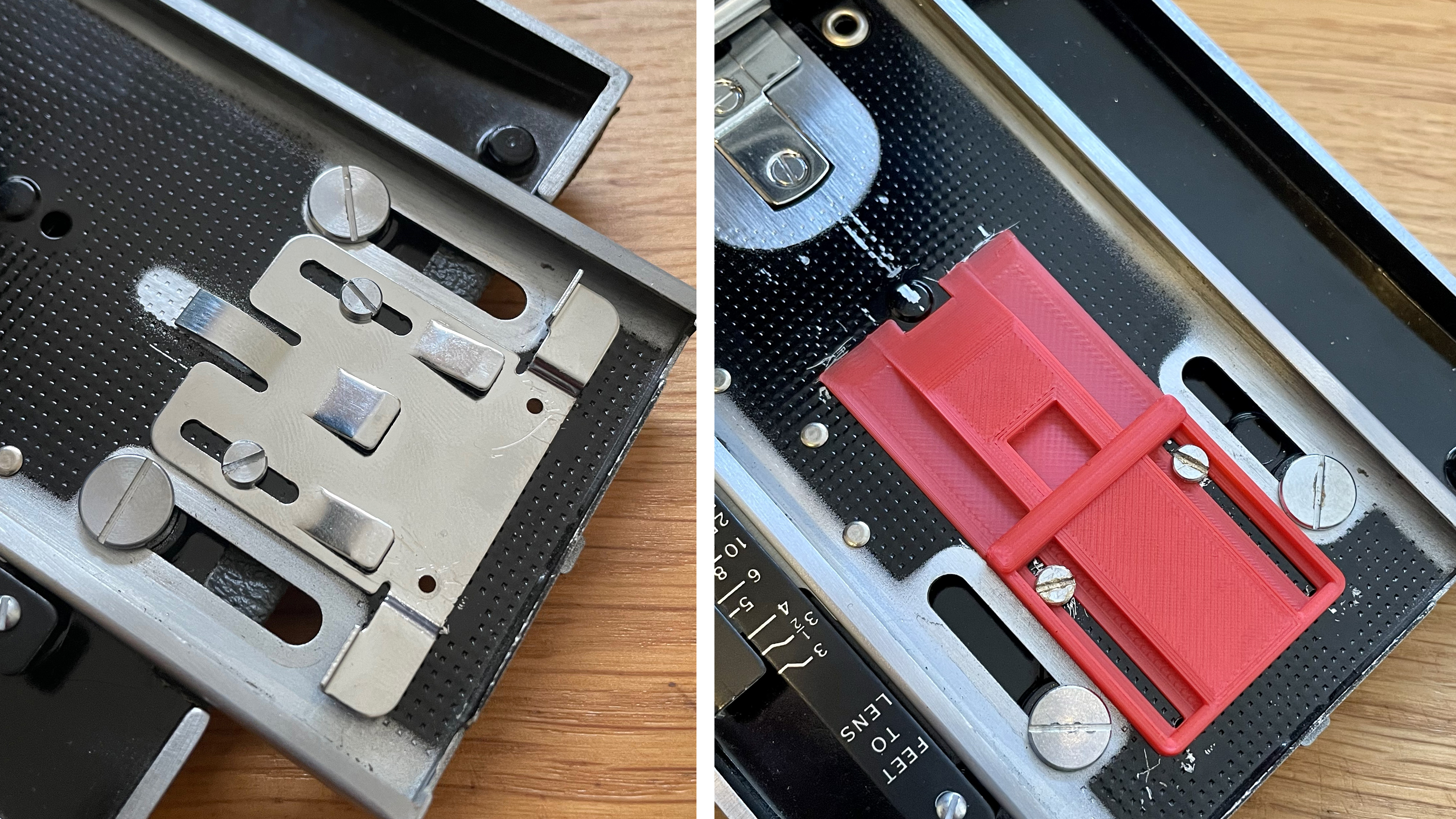
This conversion moves the film plane back by quite a bit, so we need to reset infinity. The existing infinity stop is locked into position by two rivets. You’ll need to drill these out from the back.
The existing infinity stop is unfortunately too short to do the job, so we need to replace it. Unscrew the infinity stop, keep both screws, and mount the new 3D printed infinity stop, screwing it in (but not too tightly yet).
For the 800/150 there are some out there with an infinity stop that looks exactly like the 110s, but I’ve come across a version where the infinity stop is held in place with four rivets and no screws, and the holes that are present after removing this aren’t threaded so you can’t hold the new infinity stop in place with screws. You’ll need to find infinity by locking the lens into the loose 3D-printed infinity stop, mark that, slide the lens back, and then superglue the infinity stop in place. My advice is have a close look before you buy an 800 or 150 and make sure it doesn’t have this style of infinity stop.
Step four: Get the rangefinder cover off, ready for alignment
You’ll need to remove the rangefinder cover before you mount the Lomograflok, as it will be in the way if you need to make adjustments.
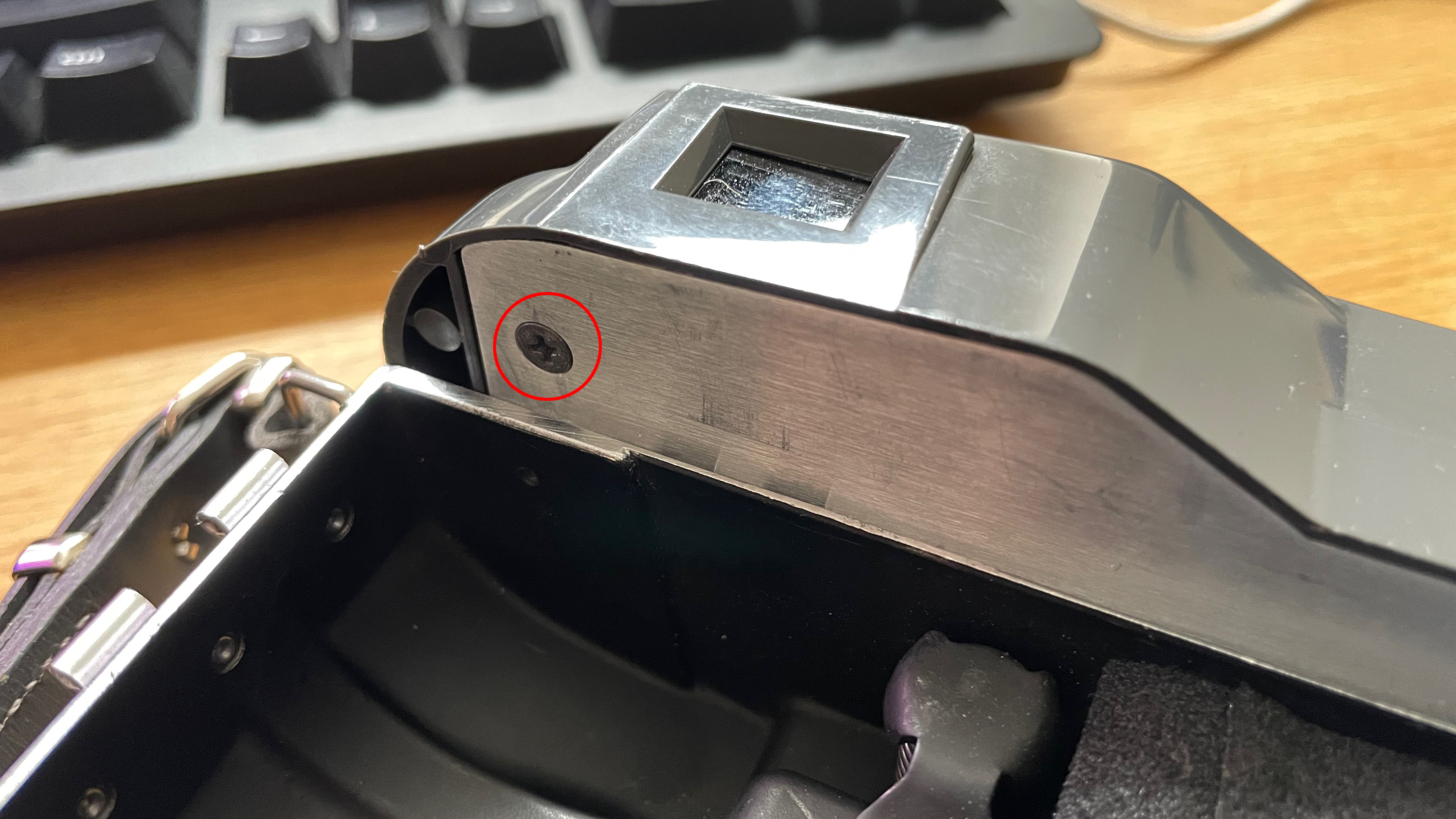
There are four screws that need to be removed (remember where each goes, they’re all different sizes):
- On the back, top left under the rangefinder, inside the camera body
- On the back, top right under the rangefinder, inside a little hole in the camera body
- On the top, right, the screw in the flash shoe (remember how it all fits together)
- On the front, with the bellows collapsed, slightly off center to the right, right under the rangefinder overhang
- For the 110a you need to remove the leather strap on the left-hand side as well
Be extremely careful when you lift off the plastic rangefinder cover. Some of the glass inserts might be loose, and the flash shoe’s wire is still attached. I cut the wire as it just gets in the way, the flash shoe is an unconventional size (and orientation), so I just use the cold-shoe adapter. I gave all glass surfaces a good clean with some residual oil remover, both those in the cover, and the rangefinder mechanism. It can make an incredible difference to the brightness of the viewfinder patch. Just be gentle as you don’t want to throw the alignment out if you can help it.
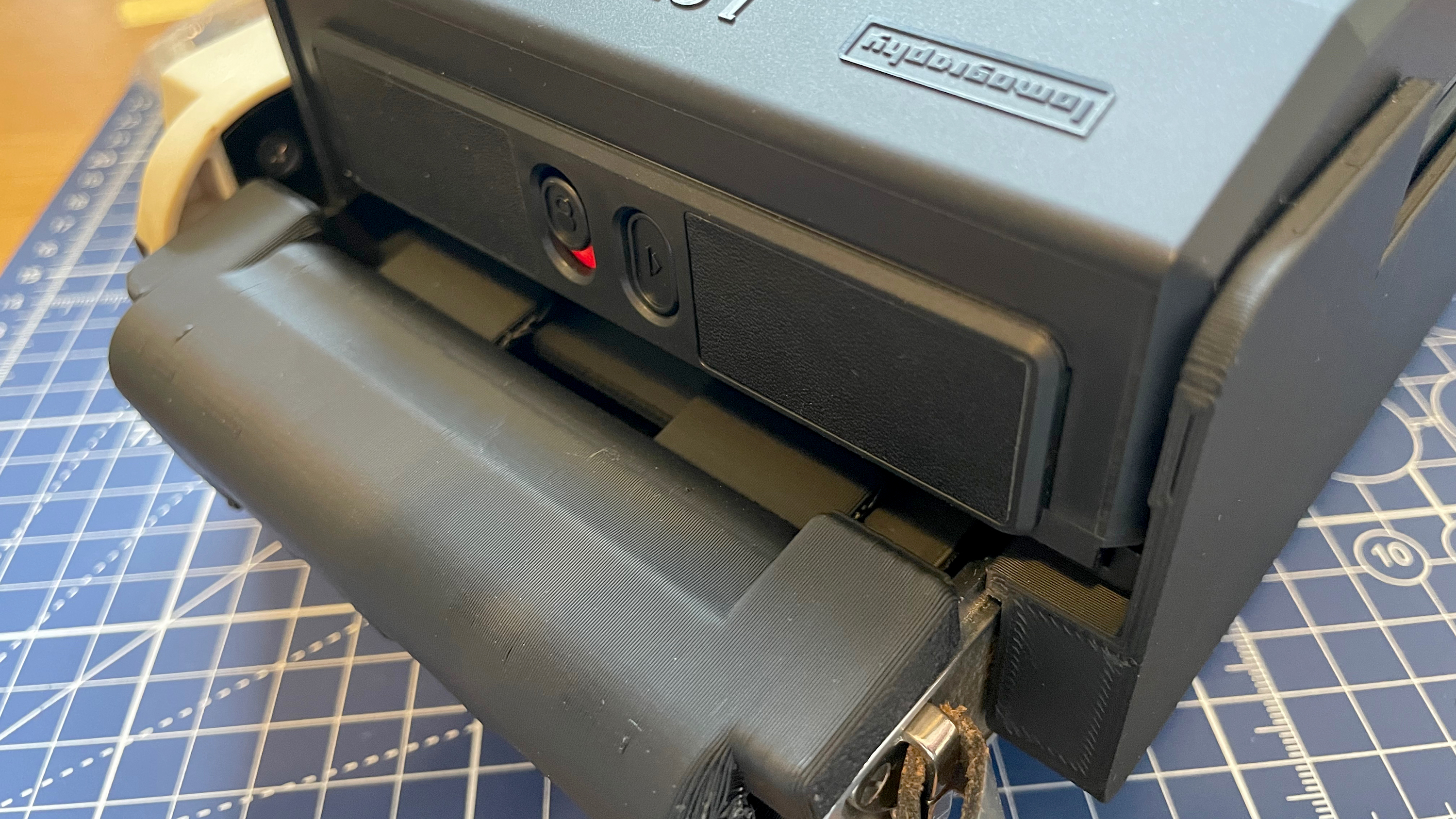
Step five: mount the Lomograflok to the camera for rangefinder adjustment
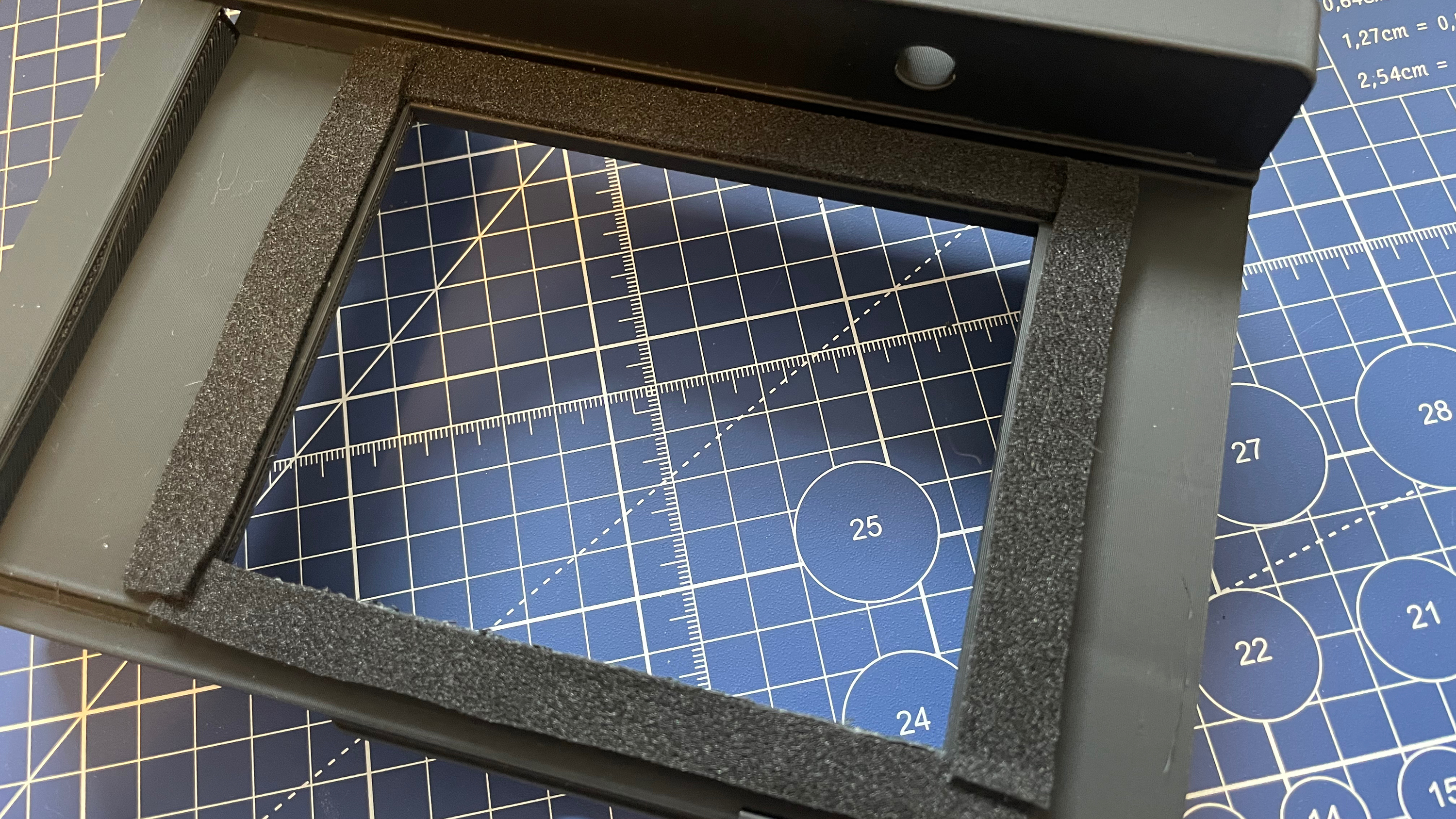
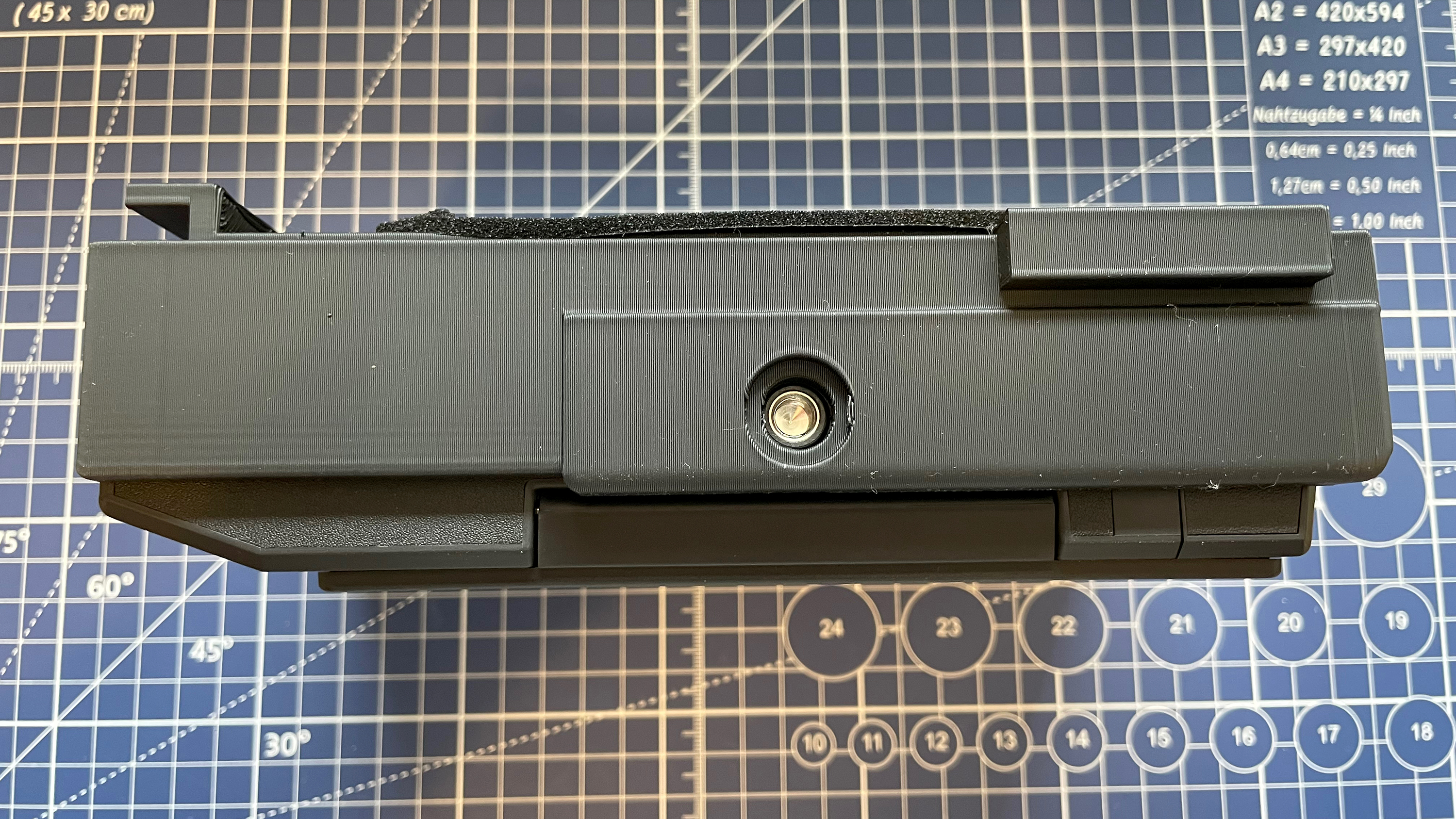
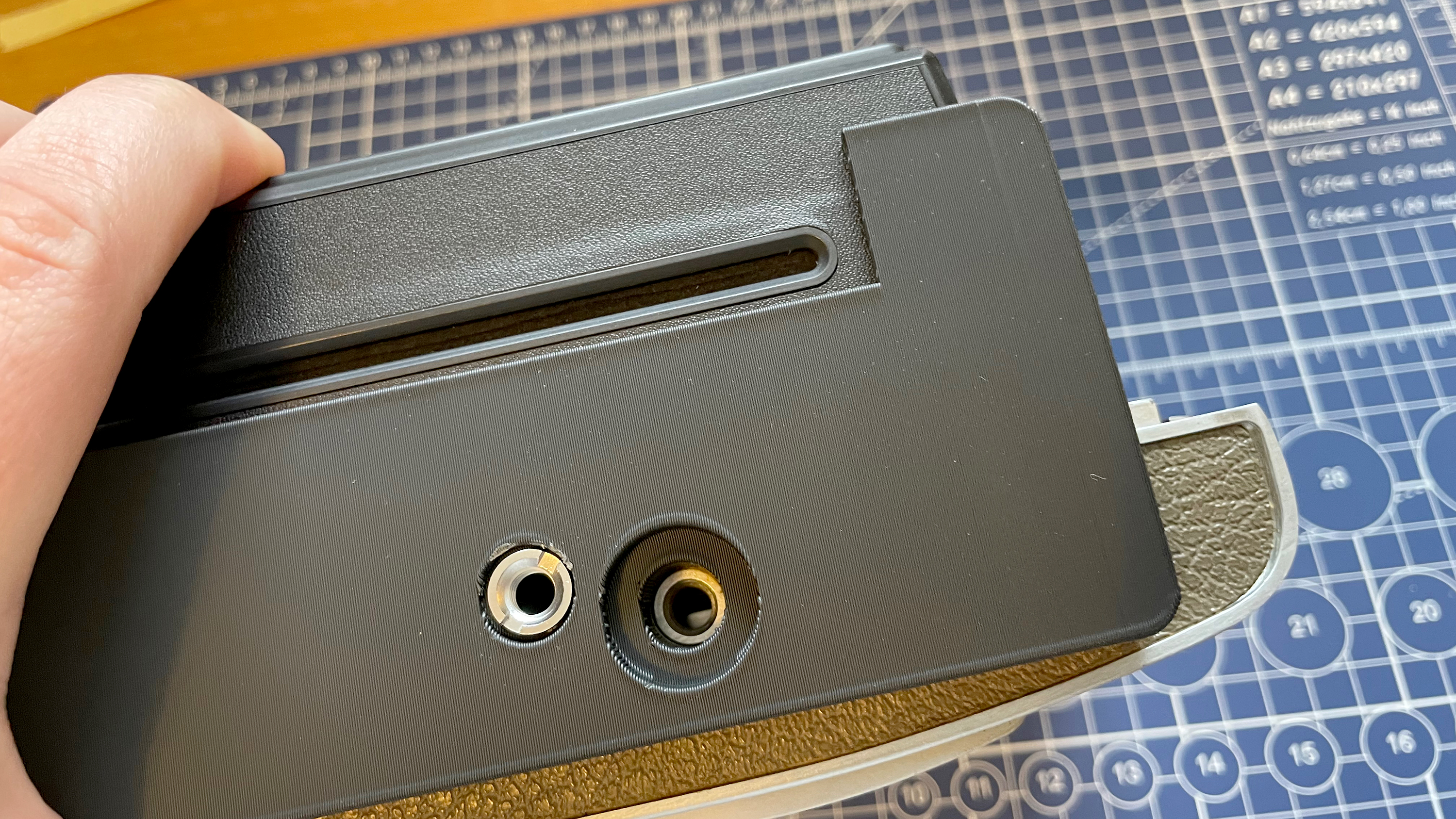
This part is easy. Before you start, measure and cut some light-sealing foam and stick it to the rectangular protrusion that faces the camera. This is also a good time to screw the 3/8-16 male to 1/4-20 female adapter into the relevant hole (with a bit of super glue to make it stay put) so we can mount the camera on a tripod to make rangefinder adjustment require less hands.
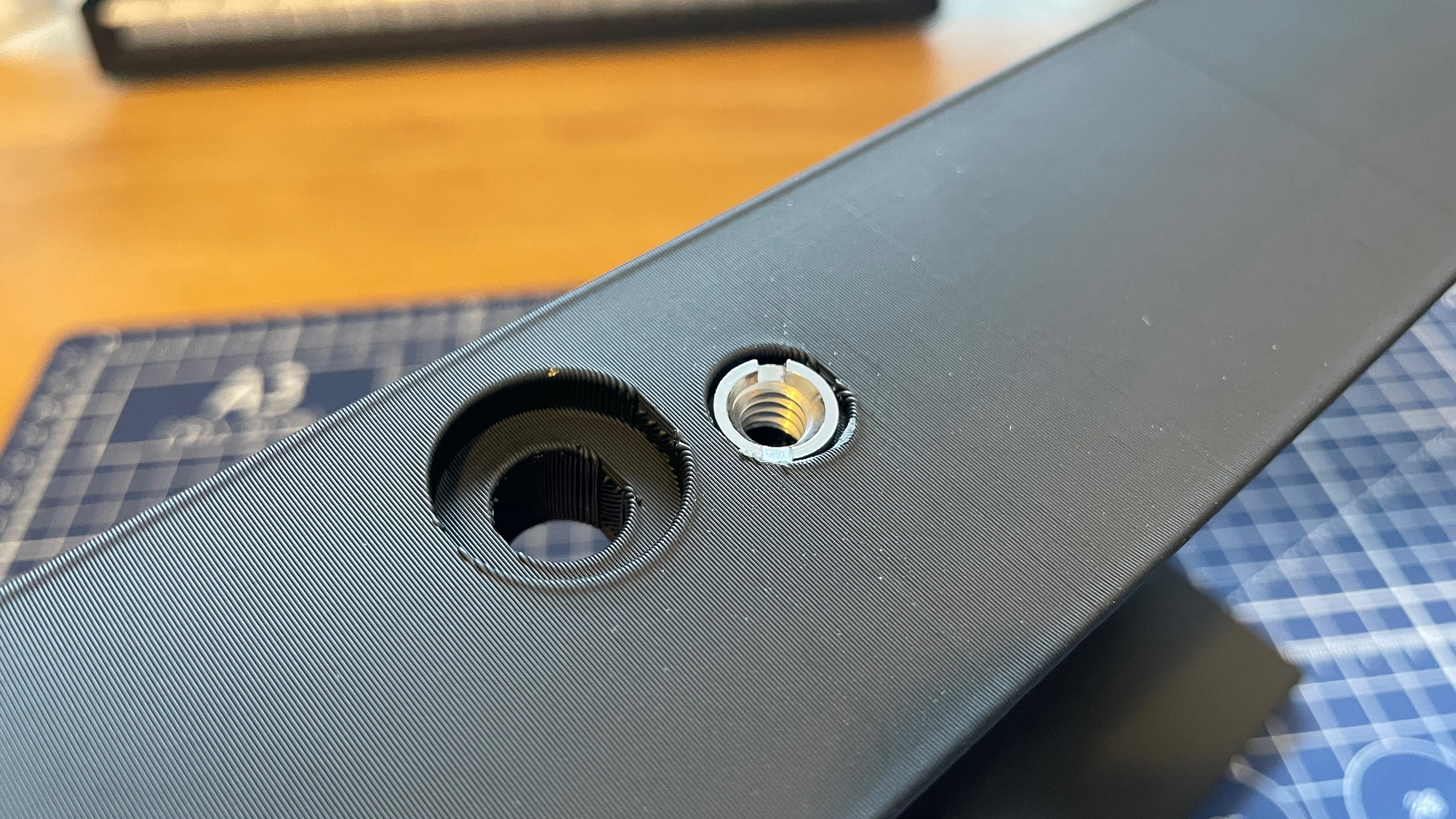
Next, remove the Lomograflok’s dark-slide. Then carefully slide your Lomograflok into the 3D printed bracket, with the buttons towards the open side. The tripod hole on the bottom of the Lomograflok should roughly align with the hole on top of the bracket. Don’t worry if they don’t 100% align, when you screw things together, everything will be pulled into the correct position, so go ahead and screw the bracket to the Lomograflok using the shorter 1/4” tripod screw (don’t over-tighten).
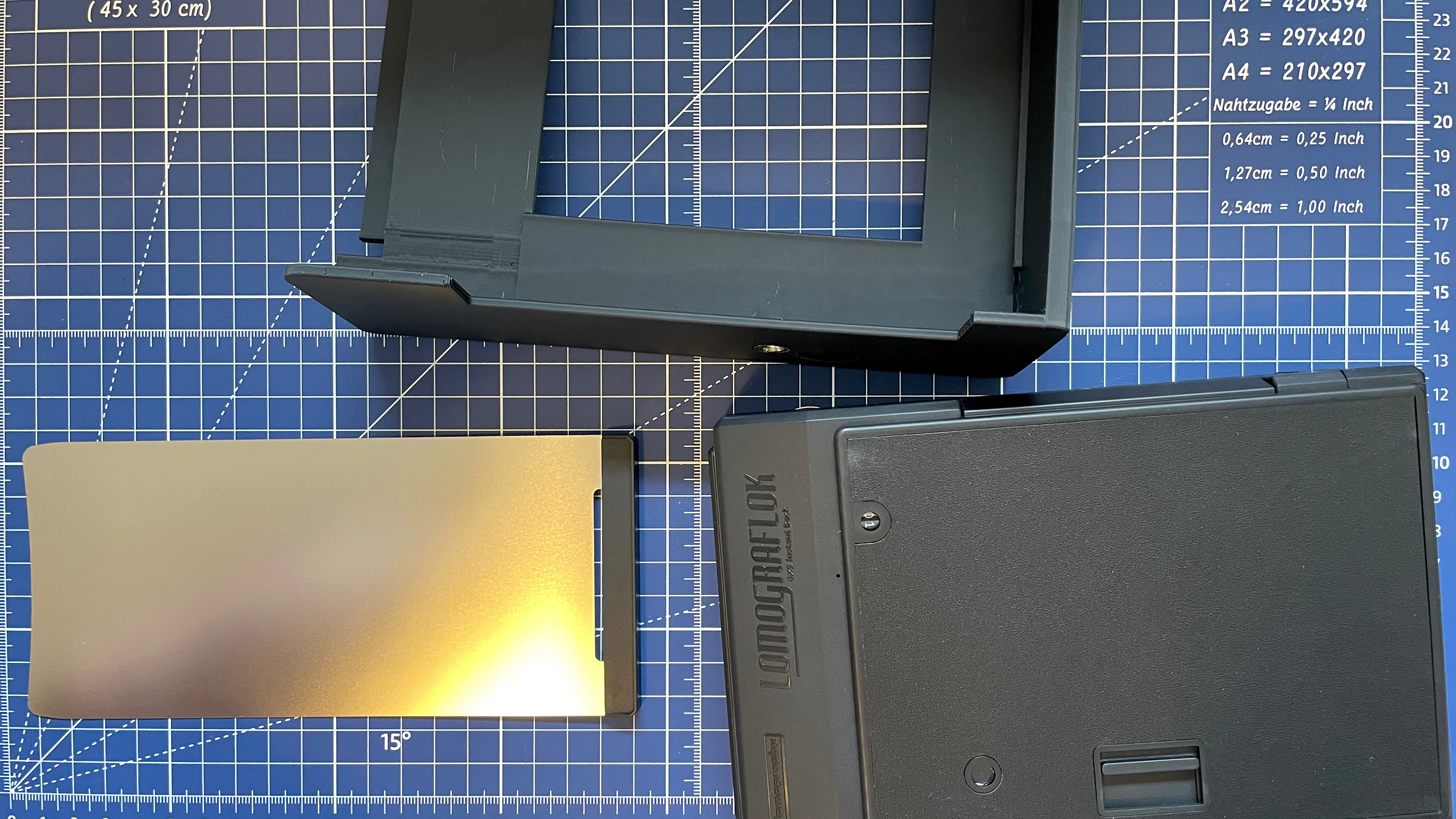
Next, rest the Lomograflok and bracket on the lip around the camera. Now roughly align the hole in the bottom of the bracket with the camera’s tripod hole and screw them together using the longer 1/4” screw. Once again, this should gently pull everything into the correct position. It should be secure, but still be careful with it as the top cover and left grip isn’t in place and they play quite a big part in keeping things where they should be.
Step six: infinity stop and rangefinder alignment
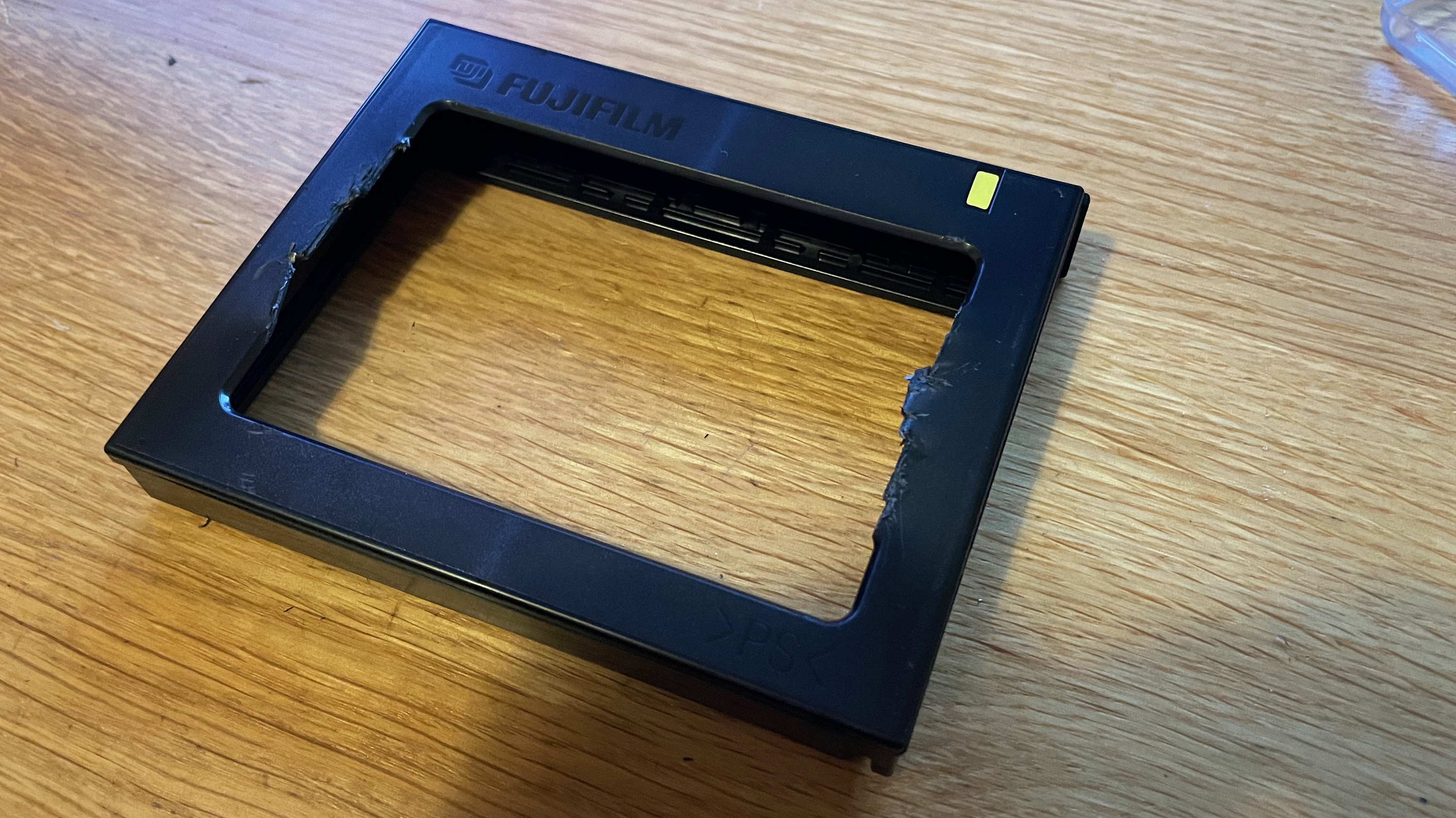
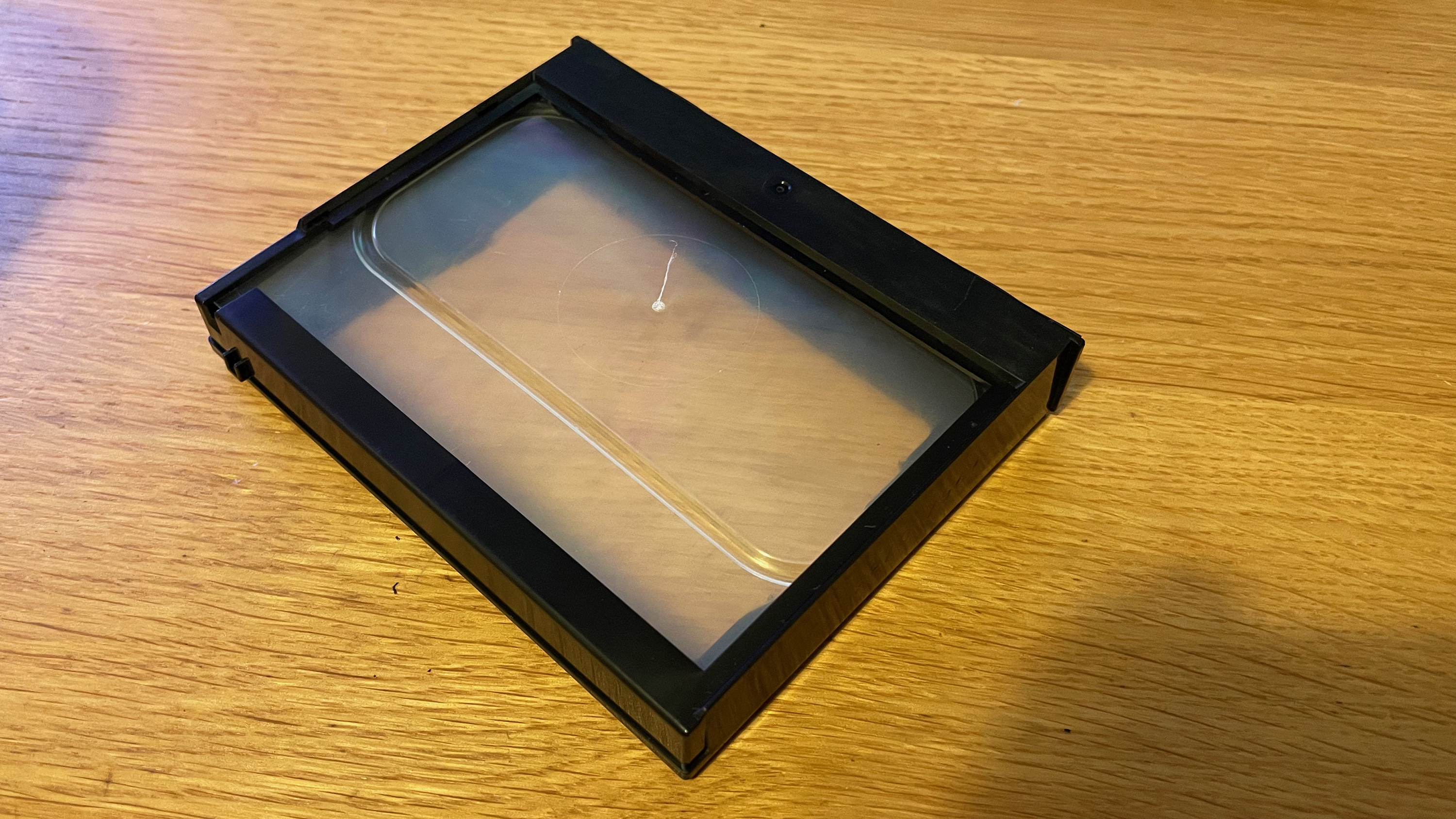
This is where things start getting exciting, but slightly frustrating. Take the empty Instax wide cartridge and cut out the strip of plastic running along the back, also removing the innards. Then tape your ground glass (or plastic takeout lid) to the inside front of the cartridge, and load this into the Lomograflok. Alternatively, there’s a printable cartridge I designed for this purpose that currently takes a Pentax 67 focus screen, but I’ve included a STEP file so you can modify it to your needs.
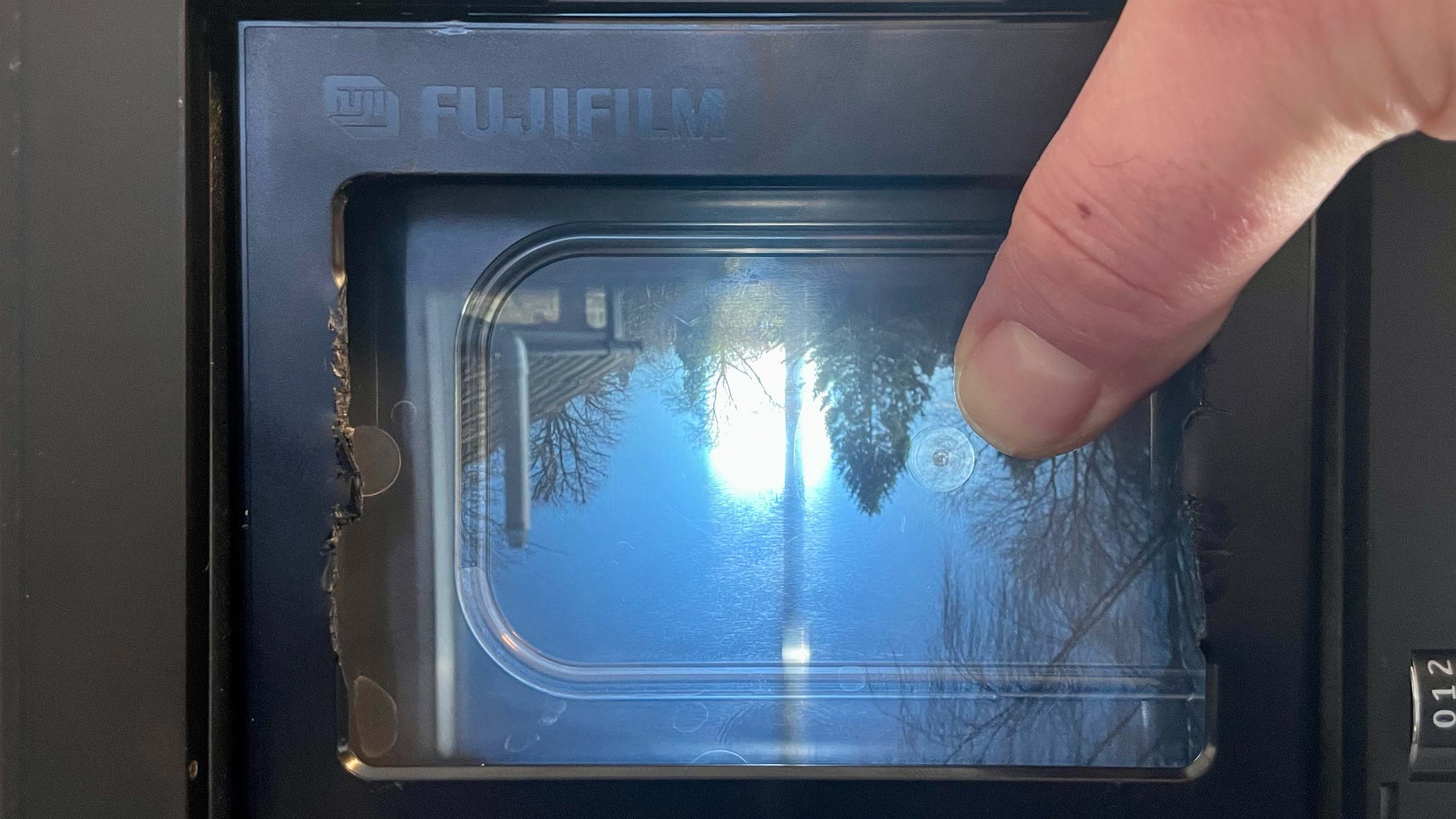
Expand the bellows and lock the lens into place, then focus to infinity and aperture wide open at f4.7. Use a cable release, put the shutter into bulb mode, and lock the release to keep it open. Aim the camera at something far away with contrast, like a telephone pole or tree with no leaves against a clear sky. With the rear door of the Lomograflok open, using the image projected on the ground glass, slide the infinity stop back and forth until you get a sharp image. This is your new infinity focus point. Screw that infinity stop down.
You’ll notice that your rangefinder is now off when the lens is focused to infinity, so we need to adjust that. The goal is to make the rangefinder “images” line up at infinity and close focus.
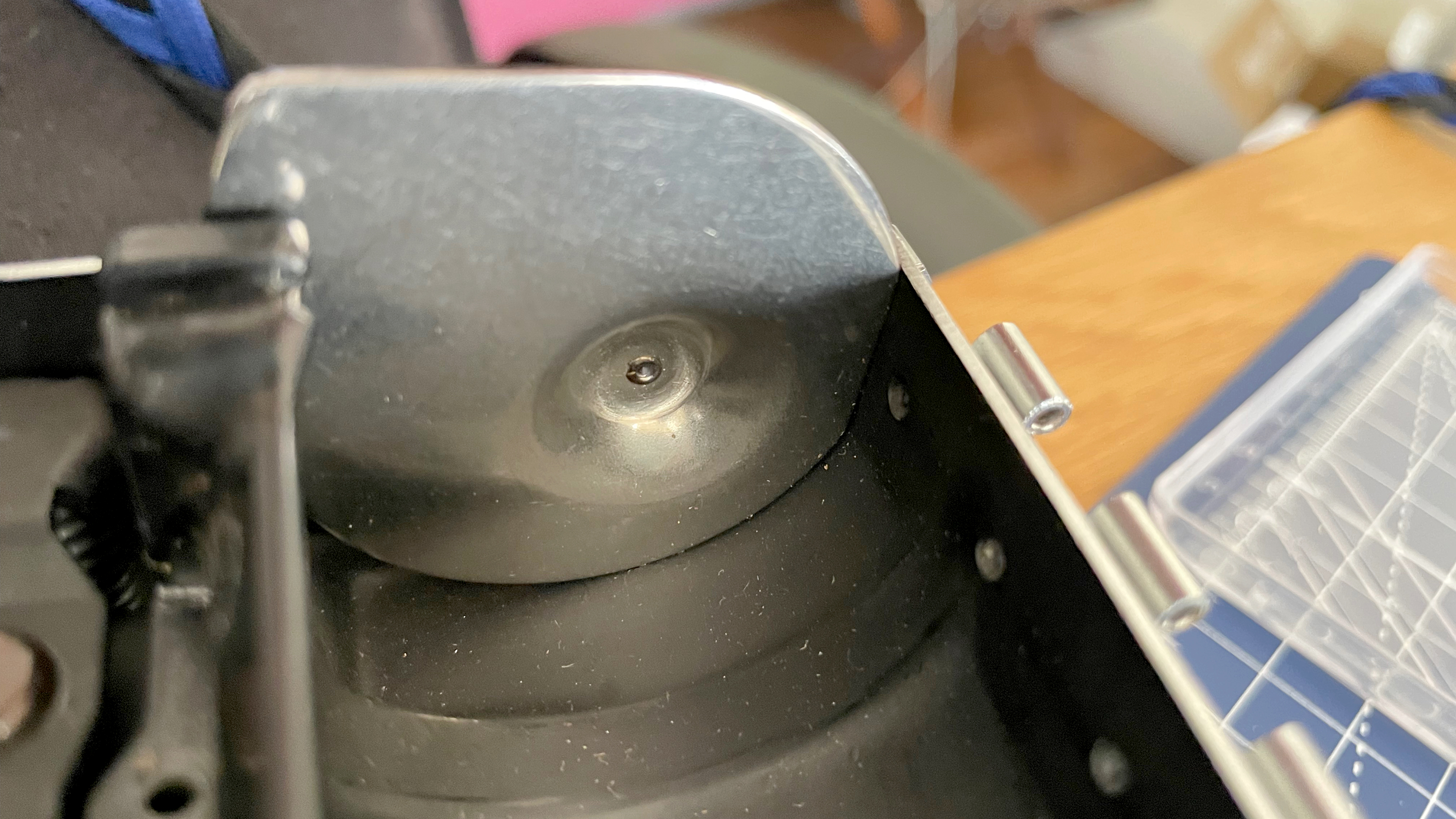
The first step is to dial in the horizontal alignment by adjusting the small screw on back of the mirror that is moved by the rangefinder arm. Turn it very slightly in both directions, until the rangefinder images line up.
Next, set the camera to closest focus, and adjust again as needed. Once this is done, go back to infinity and make further adjustments. You might need to unscrew the infinity stop and reset infinity again. It’s a bit of trial and error, but go back and forth and eventually everything should align.
If you need to make vertical adjustments, you can do so by using the screw behind the beam-splitter. This process is much easier on the cameras where the viewfinder and rangefinder are separate.
If you’re having difficulty getting it to play nice at both infinity and close focus, you might need to slightly adjust the rangefinder cam. This is on the right side of the mechanism. It has a single screw keeping it in place. You’ll also see a mark on top where the rangefinder arm meets the cam. The line on the cam is normally supposed to line up with the cam follower when it’s set to infinity, as that “programs” the rangefinder curve for the 127mm lens. Loosen the screw just enough so the cam can be adjusted and do the whole dance again at infinity and close focus. Once dialed in, tighten the screw properly, taking care not to move the cam in the process.

Step seven: Add the grips (optional, but recommended)
If you had the patience to print the very intricate grips, fitting them is quite straightforward. I’d recommend threading the rod through the freshly printed grip hinges first to clear out any debris. You’ll need to fit the grips before the Lomograflok.
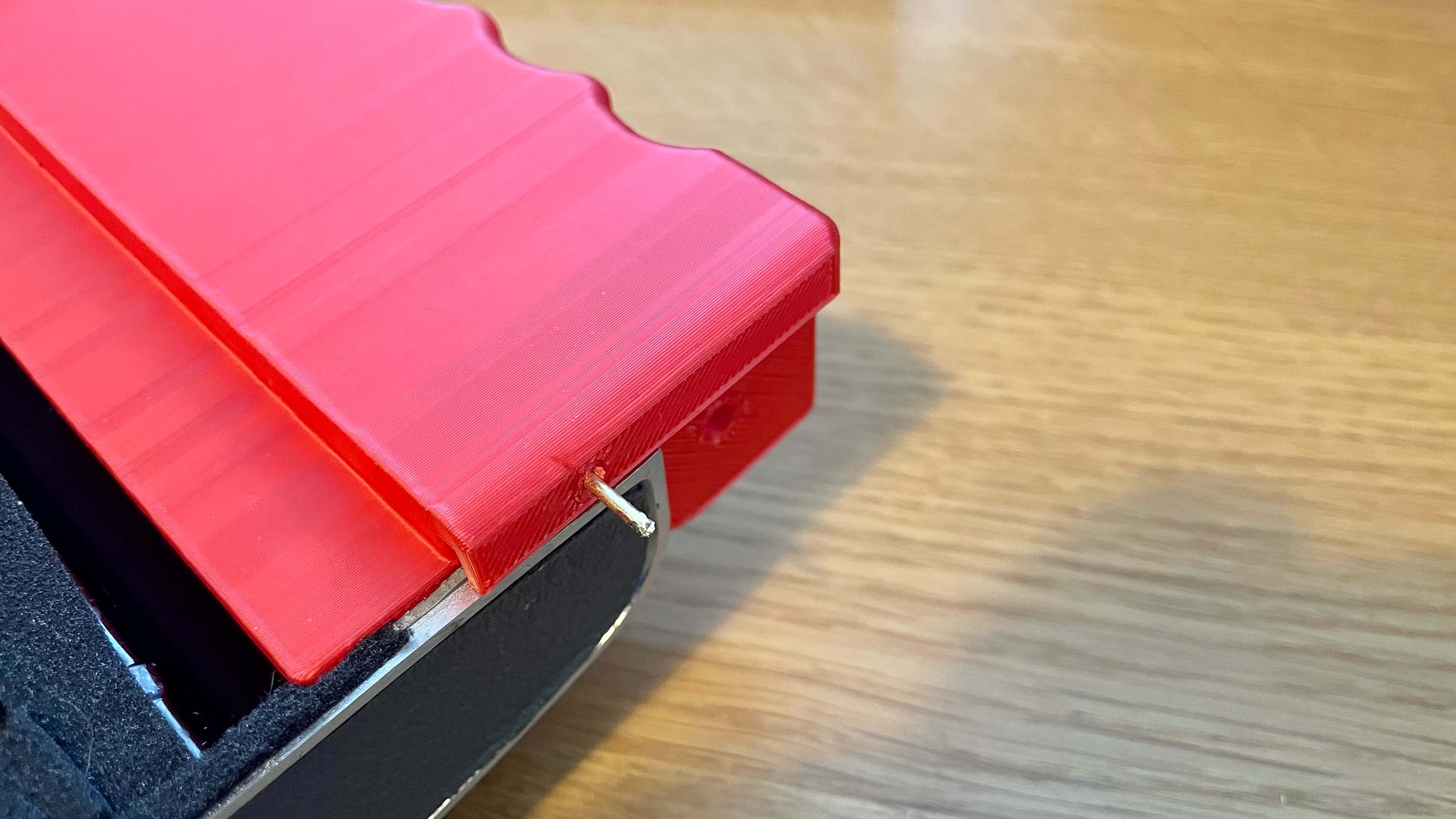
For both grips, press-fit the hinge into place. Then you’ll need to thread the rod through the hinge. Start from the bottom. I’ve found it can be a little tight, so make sure that everything is aligned, and push forcefully, but carefully. I use the pliers to help get some grip on the rod, and gently tap the last bit into place.
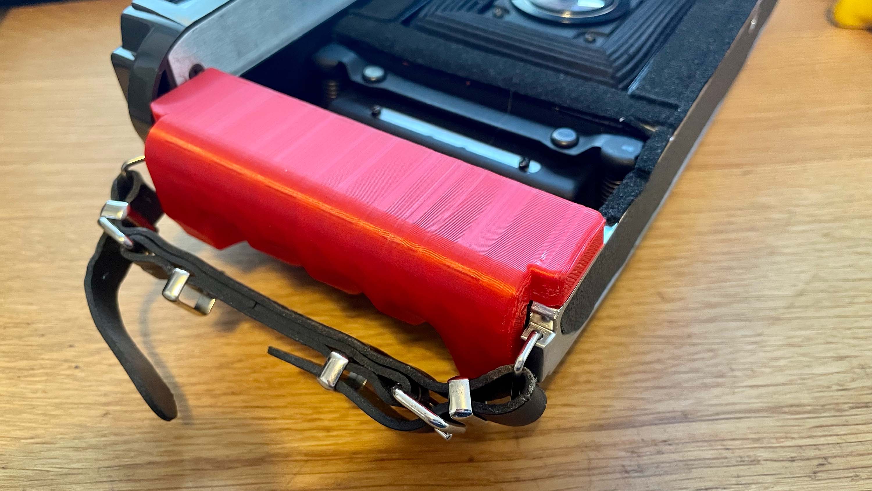
You’ll notice the right grip has a hole in it. This is to optionally fit a shutter release cable to move the shutter to a less awkward place. The trade-off here for the moment is that you’ll need attach/remove the cable release from the lens every time you collapse or open the camera.
There are specific grips for the 110b and 110a bodies I’ve worked on, but since then I’ve learned there’s no set rules for which grips will fit. Polaroid/Yashica seem to have mixed and matched parts across the whole range, which means that if a grip you print doesn’t fit, then you unfortunately need to print the other version and try that. What I can confidently say, however, is that one of the two versions on each side has worked with every single body I’ve converted (so far).
Step eight: Wrap it up
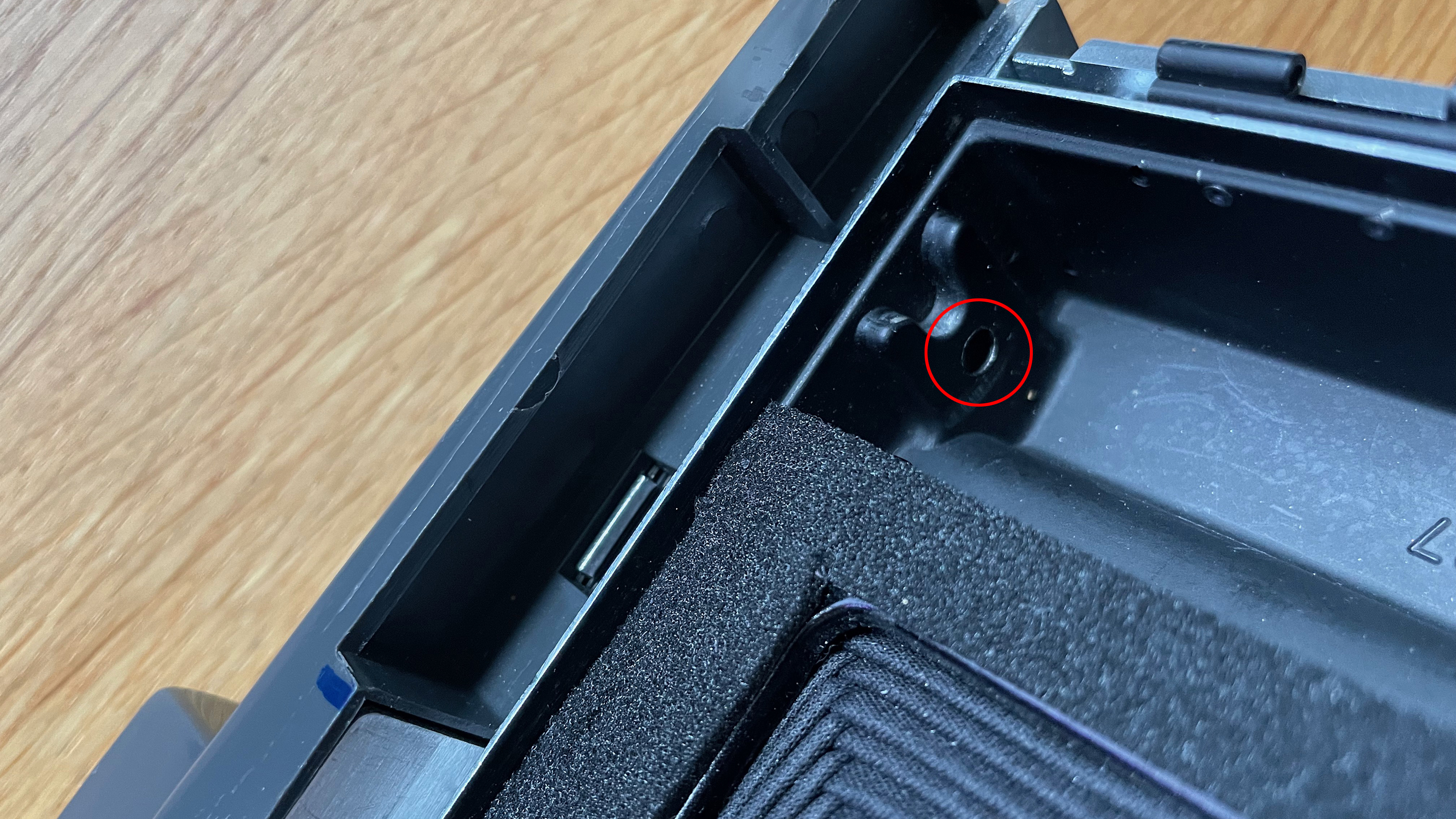
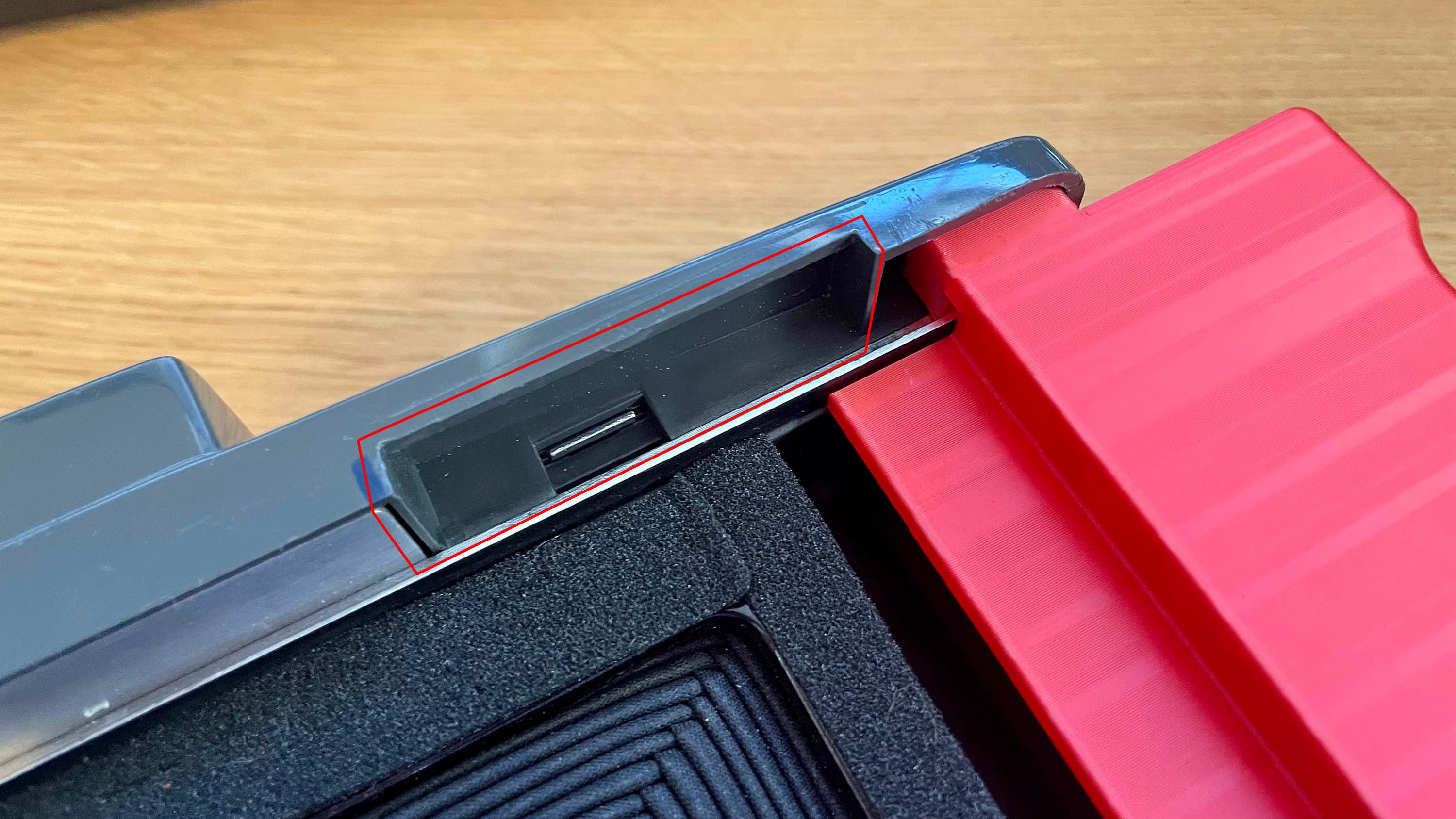
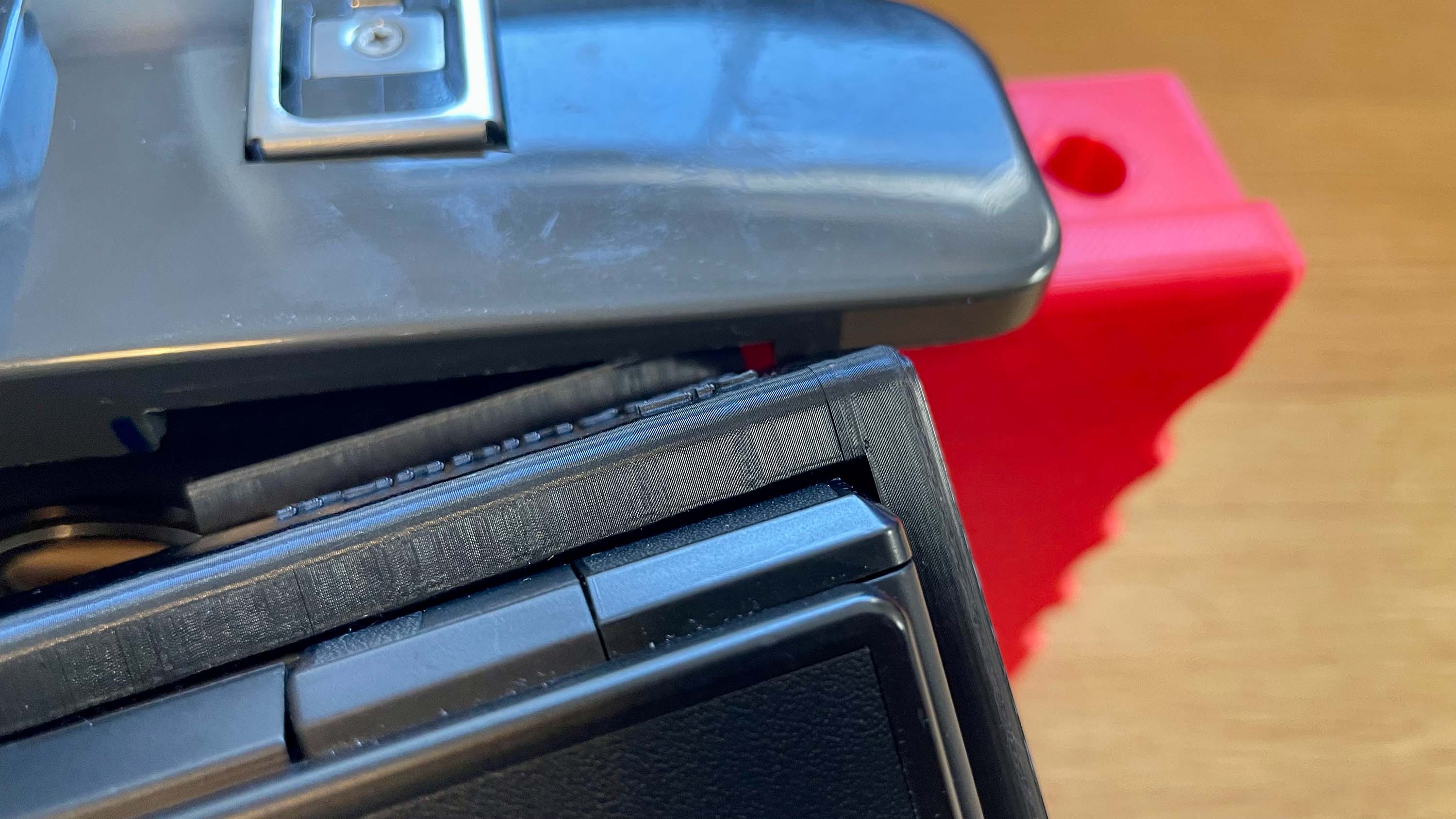
Right, we’re almost done. Remove the bottom tripod screw and set the Lomograflok with the bracket still attached aside. Replace the rangefinder top cover and all four screws. If you’ve attached the right-side grip, take care to make sure that the little bit on the top fits into the top cover, and the bracket is held into place on the left by the grip. Wait, let me explain…
You’ll notice there’s a gap in the rangefinder cover on the right, and a matching extrusion on the bracket. Tilt the Lomograflok and bracket slightly so that this extrusion slots into the hole inside the cover. It’s a very snug fit. This is an extra measure to keep the bracket securely in place. At the same time, there’s a lip that will need to sit under the little wings of the left grip, this holds the bracket snugly to the camera on the left side to prevent light leaks on that side. This can be a little finicky, and the bracket sits very tightly once everything is in place. You might be easier to attach the left grip after securing the bracket in place. Once everything’s in place, if you ever need to remove the bracket, it will probably require that you remove the left grip first.
Now continue mounting the Lomograflok and bracket as you did before, securing it with the tripod screw. If you would like to use a flash (with sync cable to the lens) and/or a light-meter, you can also optionally mount the cold-shoe adapter.
Finally, step nine: Get out there and shoot a test pack of film!
You’re good to go! Put in a pack of Instax wide, eject the pack’s dark-slide, and take your first picture. You might find that you need to continue tweaking your rangefinder. It’s all part of the fun.
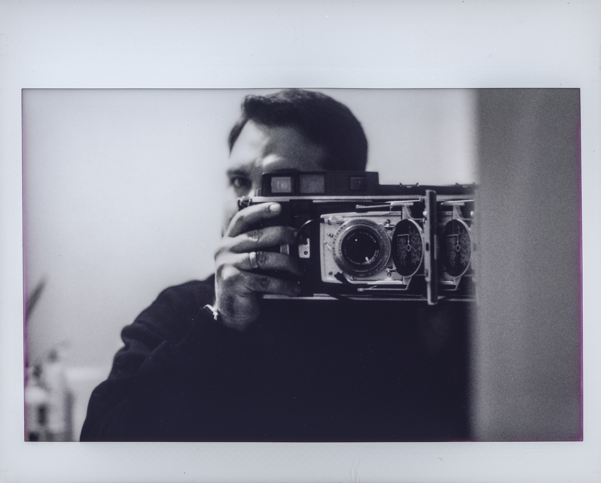
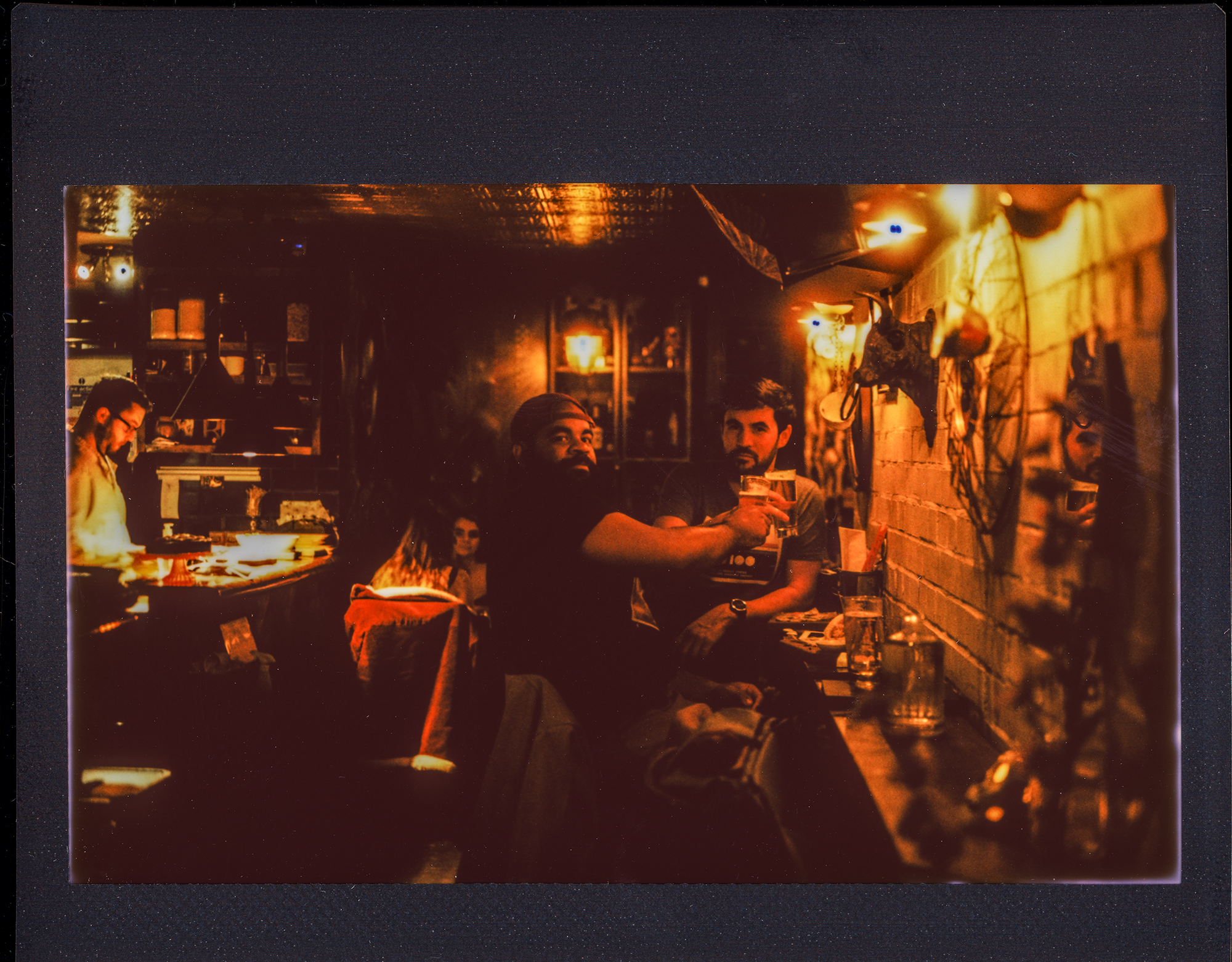
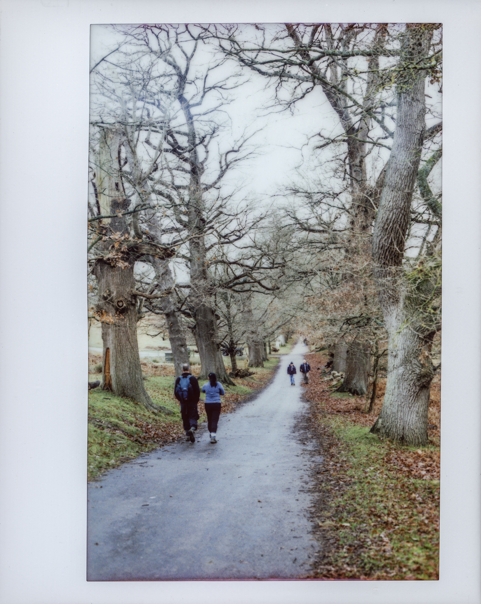
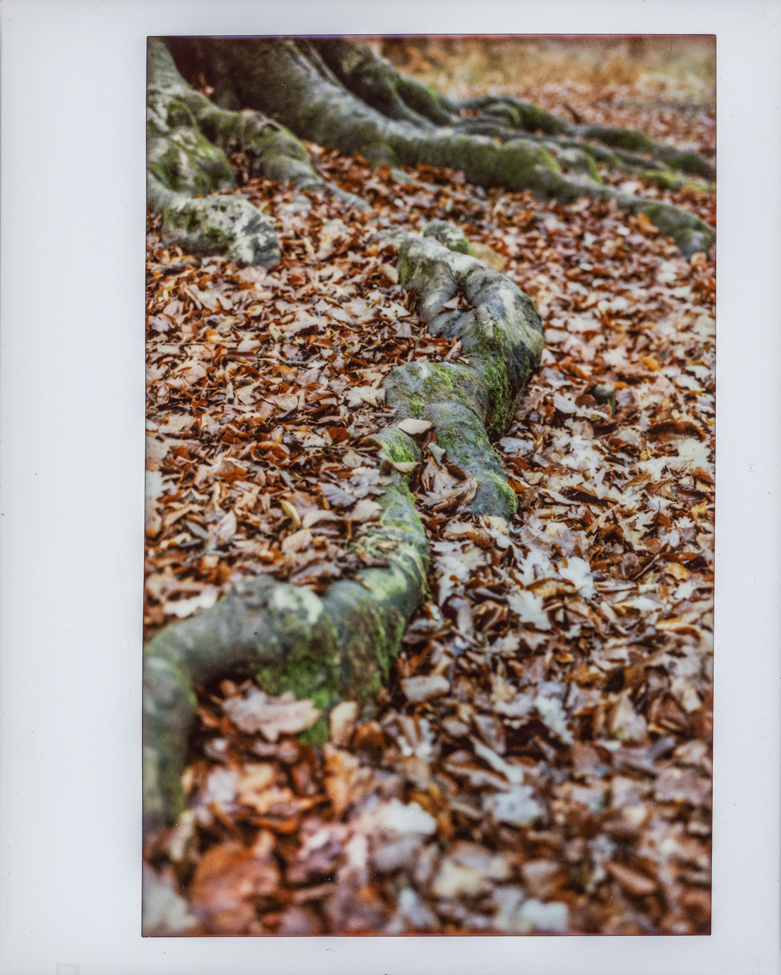
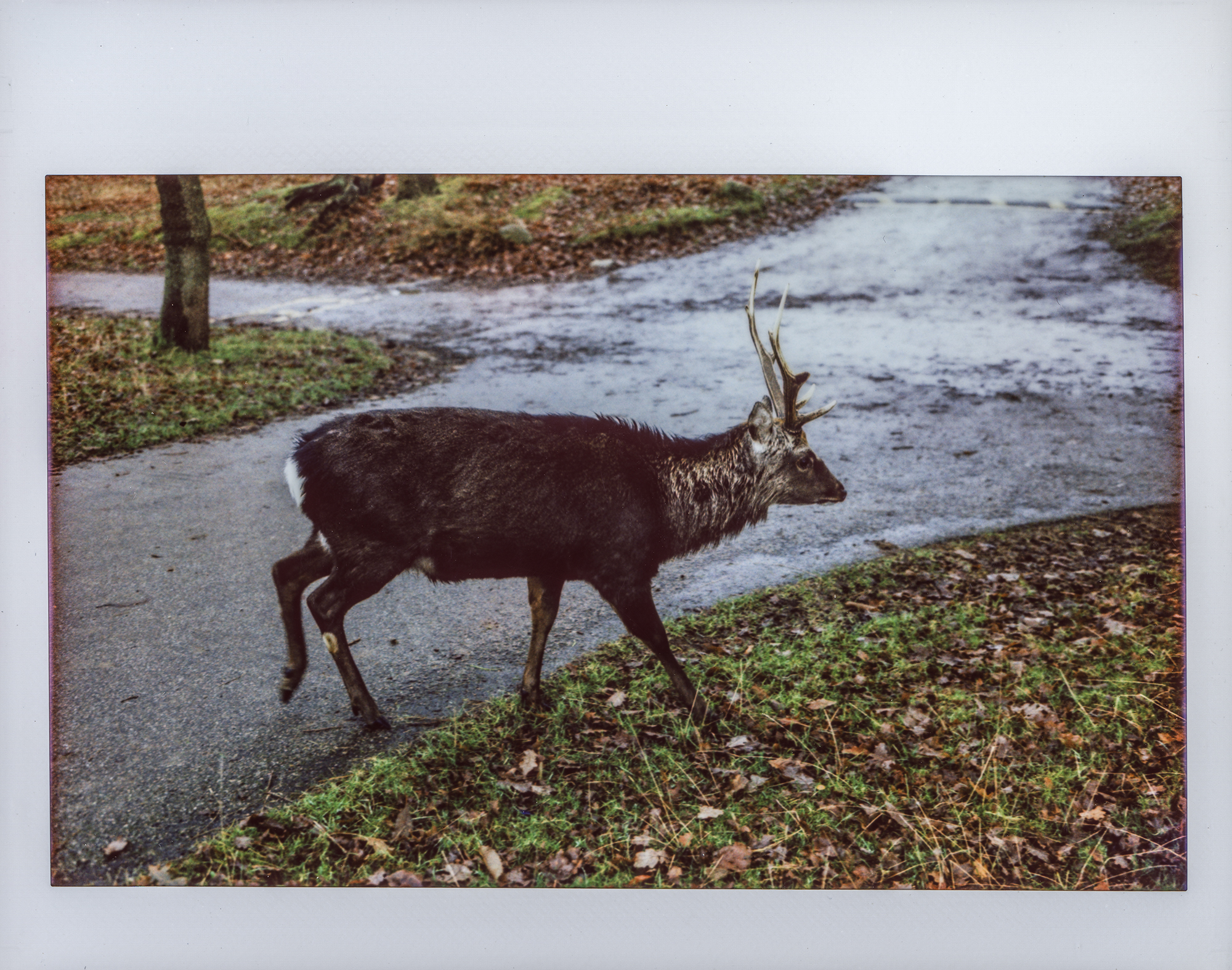
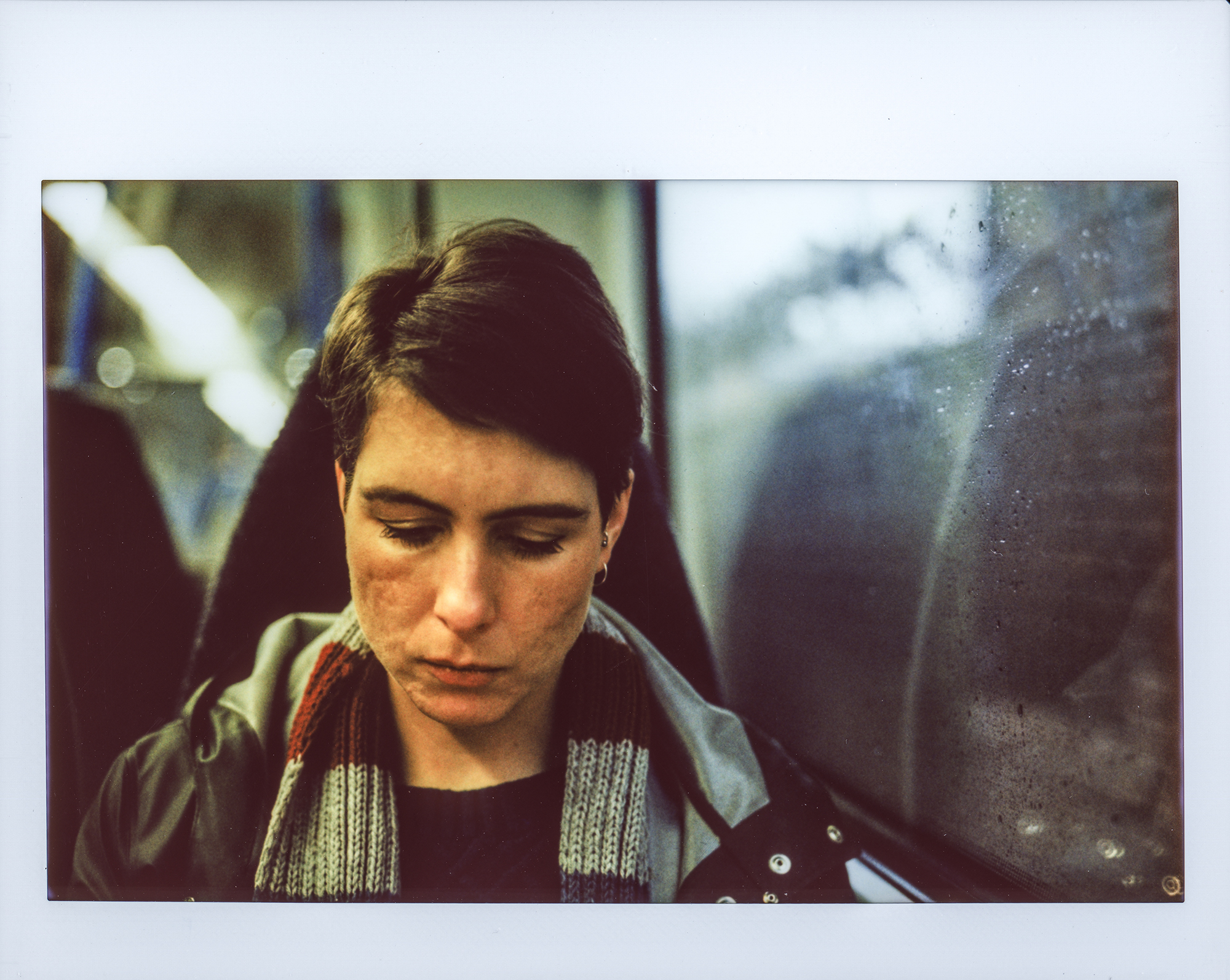
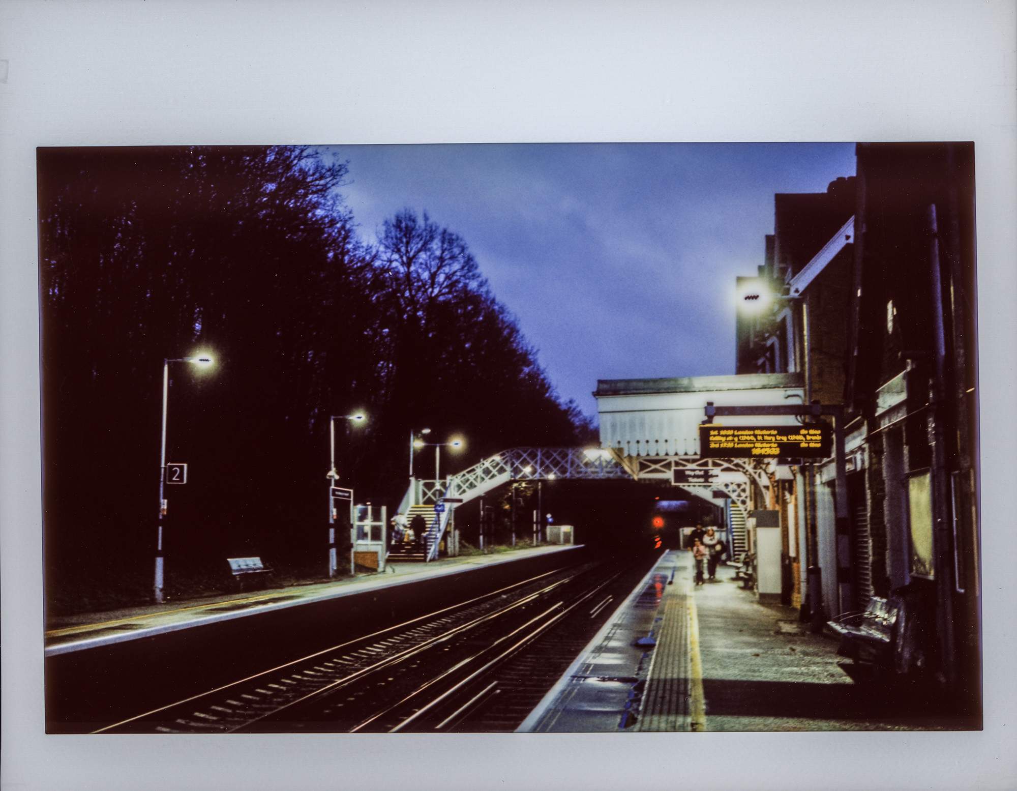
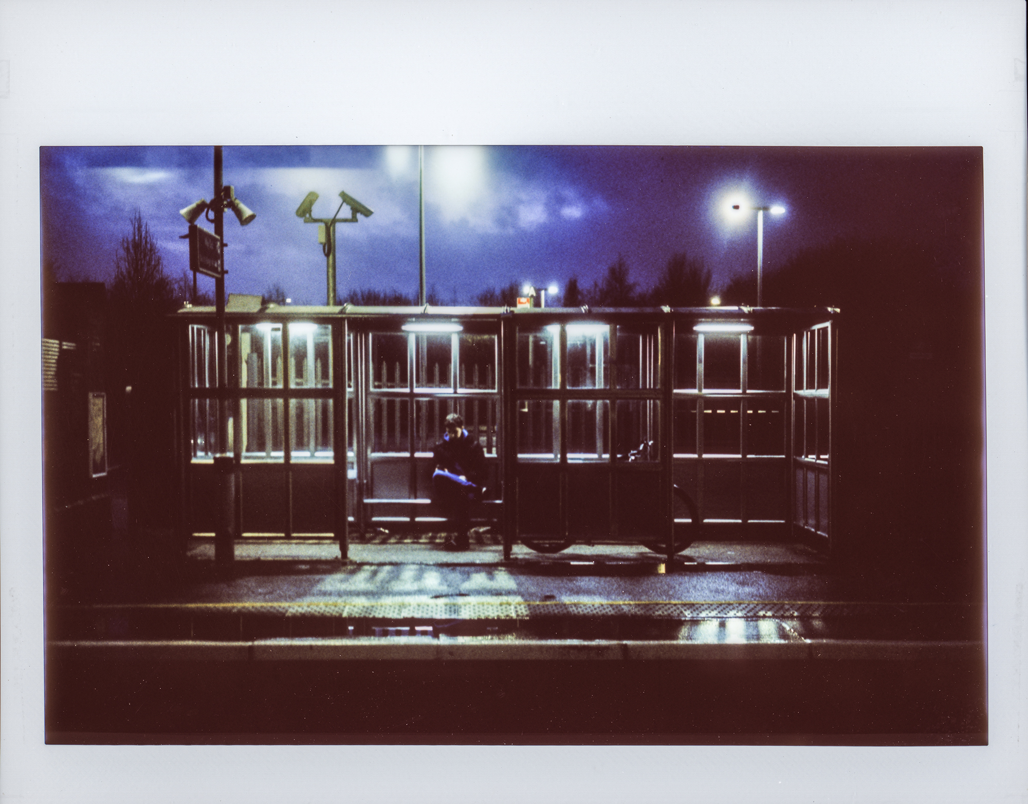
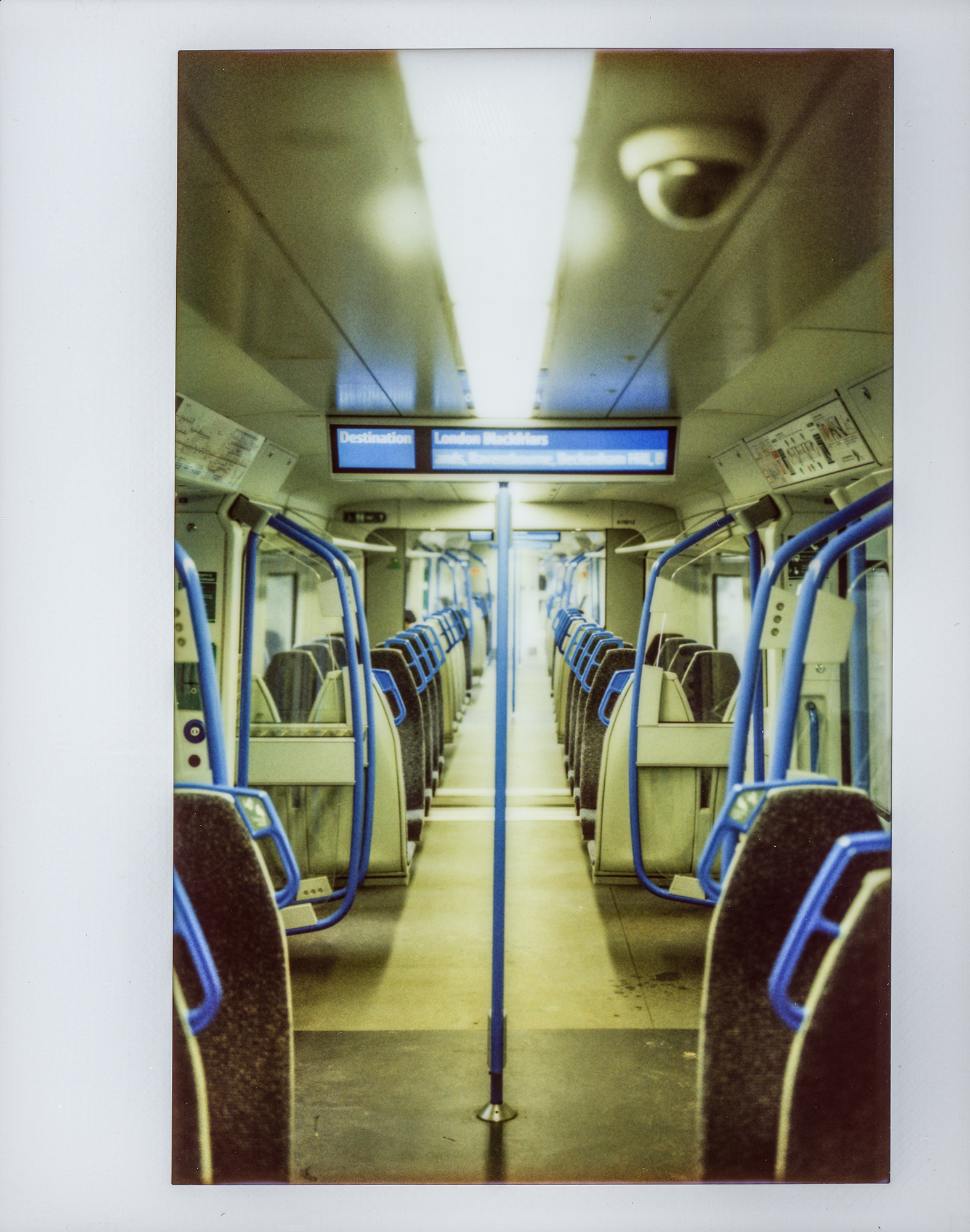
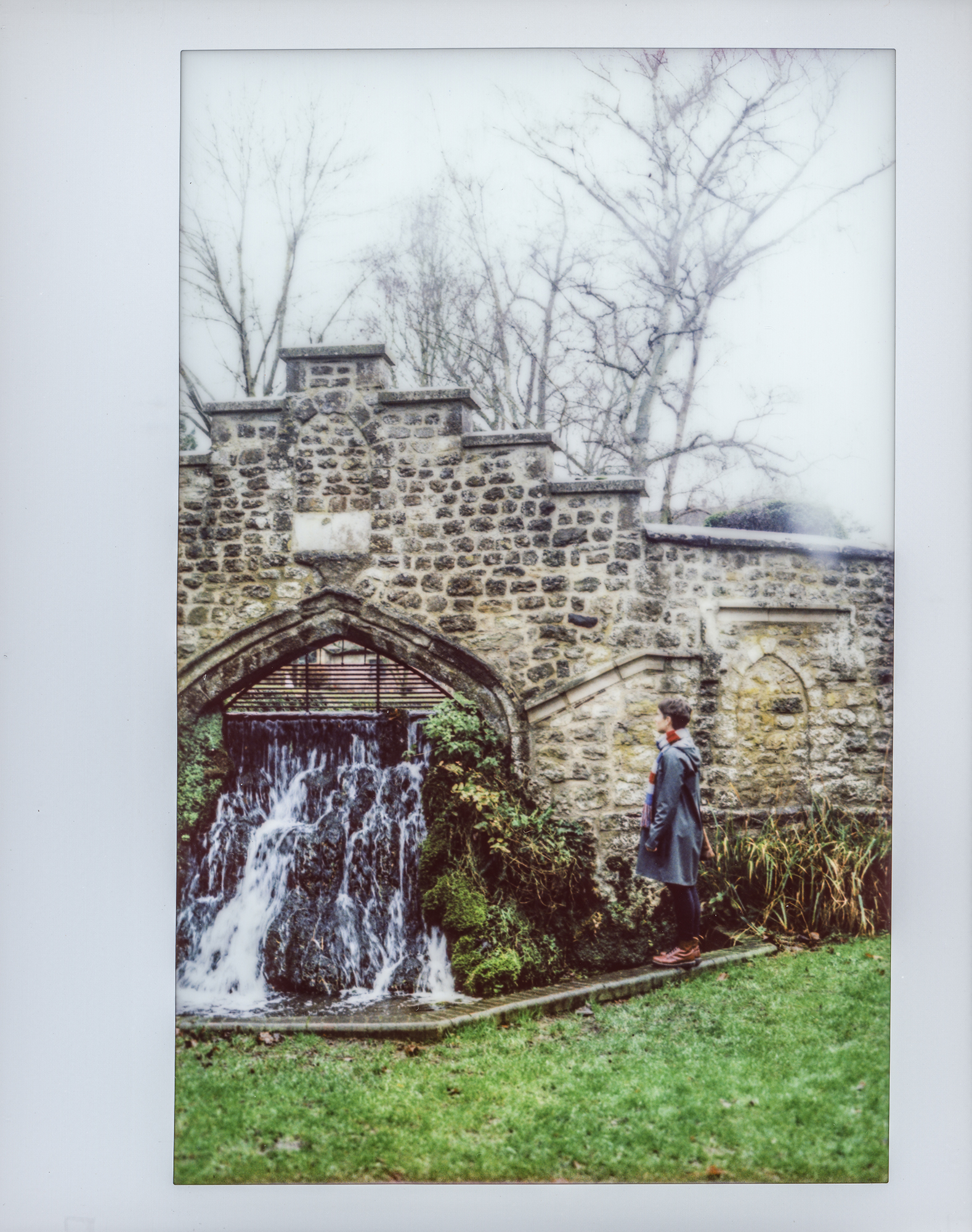
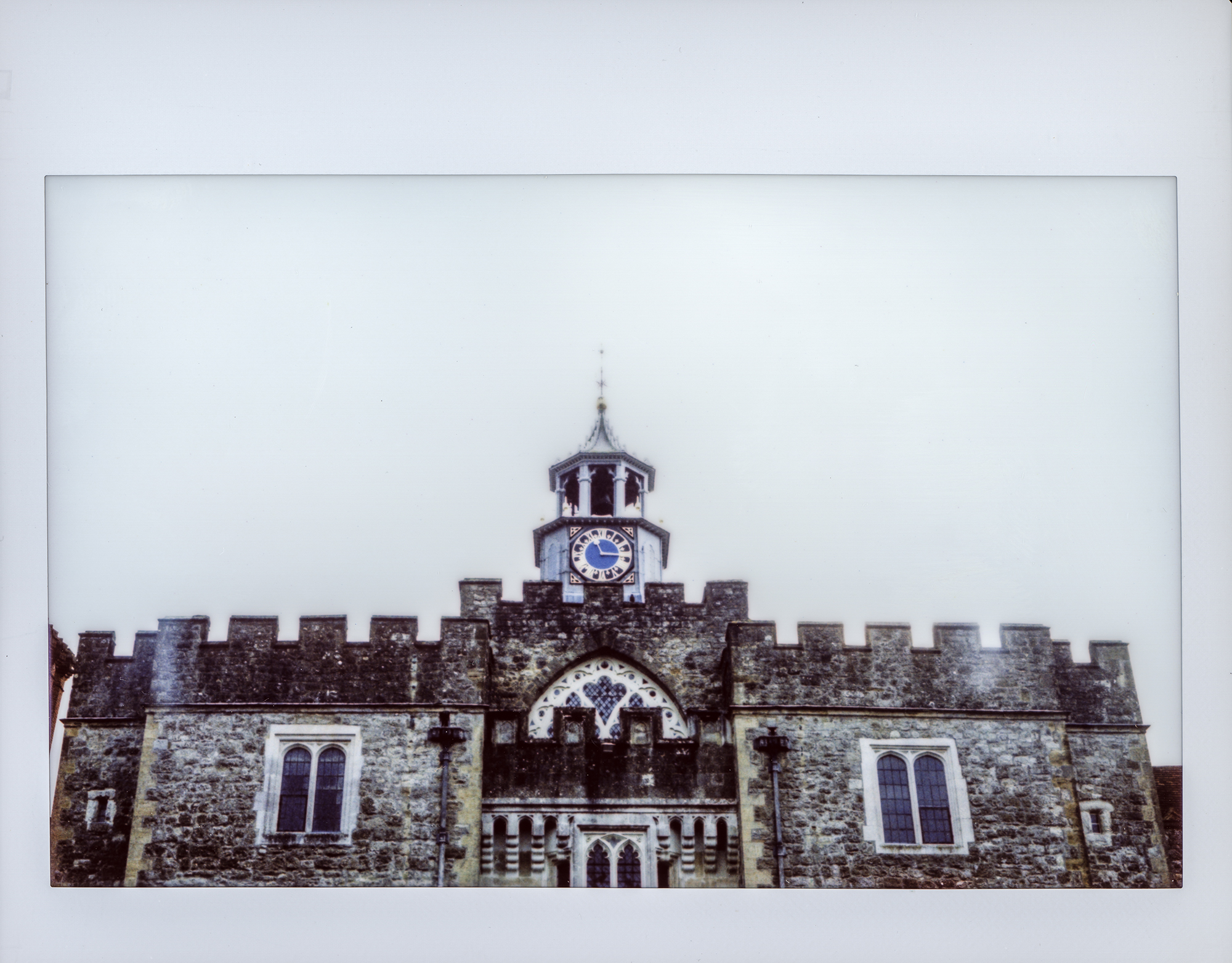
Here are a few sample photos…

A final note on the Lomograflok darkslide: You can still use the darkslide! I’ve bent mine slightly upwards at around a 30 degree angle at the handle, and this allows me to continue using it quite easily.
Conclusion
I really hope you enjoy shooting your newly converted camera as much as I do. It’s a real head-turner and conversation starter, and the perfect way to disarm subjects for very natural portraits. Even though the conversion is straightforward, it took a lot of effort to get here. The infinity stop went through about 12 iterations, and the bracket and grips have gone through countless more. At the end of the day, apart from really wanting a decent Instax wide camera, I did this to share it all for others to reproduce and improve on, and I’ve already seen some excellent conversions from the community.
Ribsy did a great walkthrough of the bespoke 110a conversion I did for him.
Jamie tackled the conversion on his own and got some pretty great results!