Home / Writing / Building a Frankinstax: a Polaroid Pathfinder 110a/110b & Lomograflok conversion
Introduction
👋 Hello! This is an old version of the build guide. A better, easier, non-destructive, reversible version is just a click away!
This is a project that started a quite while ago. I had found and purchased a Polaroid 110a with the original intention of converting it to shoot Instax wide. I ended up destroying three Instax Wide 300s before getting to a point where I successfully mounted a horribly fragile bodged back to the 110a, using some plywood and way too much Sugru. It was a difficult conversion that involved cutting away part of the 110a’s body (going through who knows how many Dremel metal cutting discs). I ended up with something that really took surprisingly good photos. Sure it spat out skew horizons, it was difficult to frame photos accurately, and it wasn’t pretty to look at, but it proved one thing: give Instax good glass and it sings.
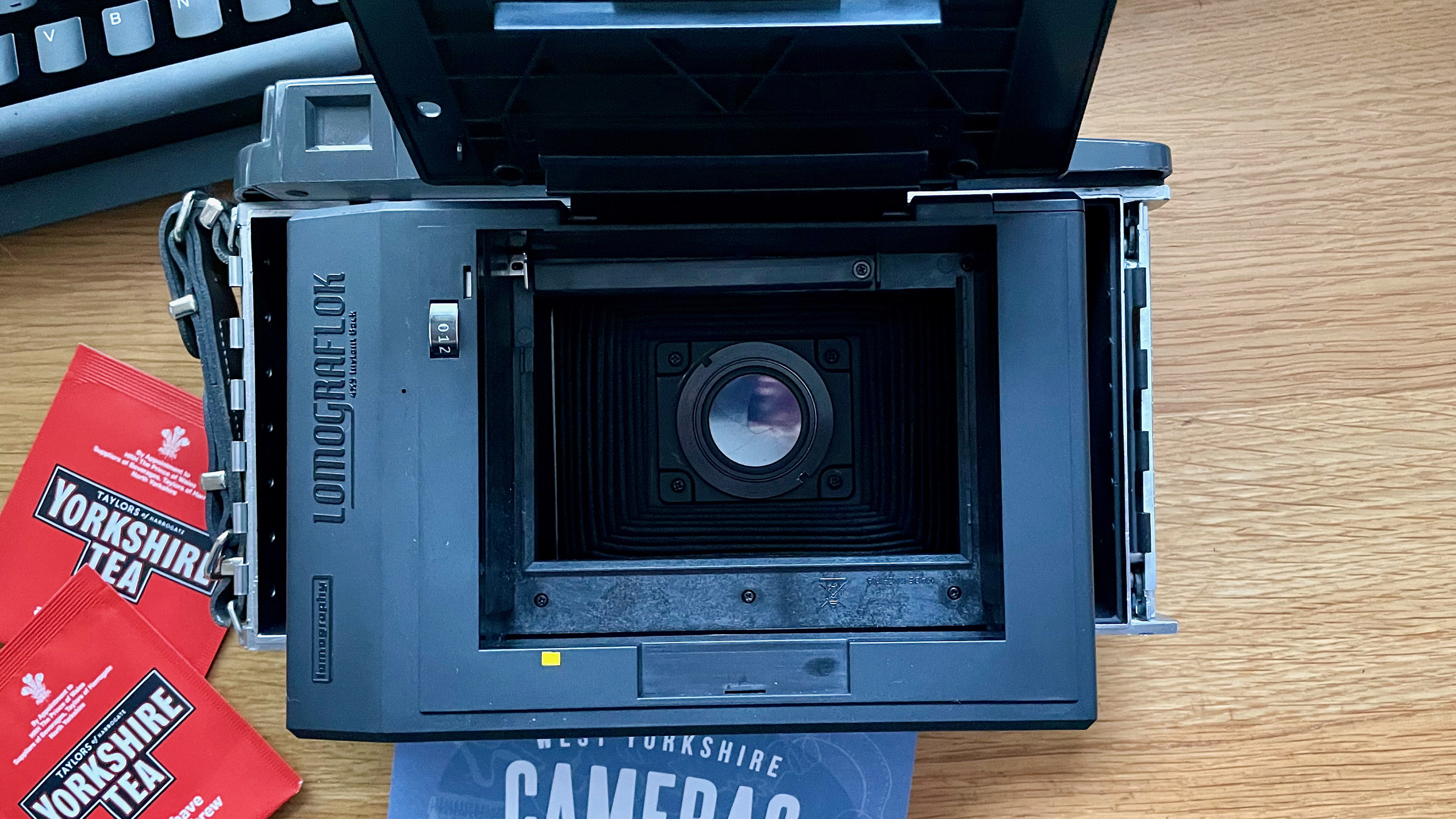
And then Lomography surprised everyone with the Lomograflok. Of course I preordered one right after it was announced. Although the original intention of the back was to bring Instax to 4x5 cameras (and it does this very well), even before release the usual makers (like Ethan Moses and Steve Lloyd) spotted the potential of this device to be paired with good lenses to create a serious portable solution with incredible results.
So there I was, browsing new stock on the West Yorkshire Cameras website as one does, when I saw a Polaroid 110b kit for a very good price. The idea had been brewing in my subconscious to redo my original “Frankinstax”, removing the flimsy, hacked apart Instax camera and finding a reliable way to mount the Lomograflok, but a fresh start with the improved 110b would be even better. So I bought it. When it arrived I was surprised at how well the two fit together. And here begins our journey…
Before we start
A few caveats
Before we get stuck in, there are a couple of things you should know:
- This is a destructive conversion, but relatively easy compared to the other, older methods out there (I find this acceptable as the film for this is long gone, and we’re giving the camera a new lease on life)
- Because of the 110b and Lomograflok’s geometry, and how this conversion was designed, your pictures will be “upside down”, with the wide part of the frame on the top (I quite like the different look it gives)
- Framing is slightly off, but you get to know by how much quite quickly
You will need
Tools:
- Sturdy pair of pliers to modify the camera’s bottom lip
- Drill with a small bit to drill out the infinity stop rivets
- Dremel with a metal grinder attachment or very rough (but precise) metal file
- Fine metal file
- A set of precision screwdrivers
- You might need a hammer
- 3D printer if you intend to print the bracket and new infinity stop yourself (optional)
Parts:
- A Polaroid Pathfinder 110b (or 110a - the bracket fits without issue, but there are two small differences that are highlighted in the necessary steps)
- A Lomofraflok Instax wide back
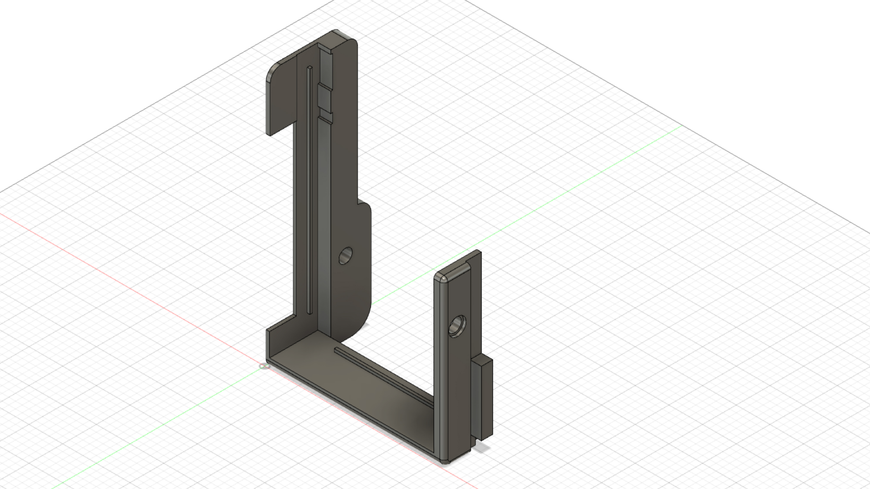
- Lomograflok / 110b mounting bracket (3D printed, there’s a version for use with a tripod and without, print the one you prefer)
- Modified infinity stop (3D-printed)
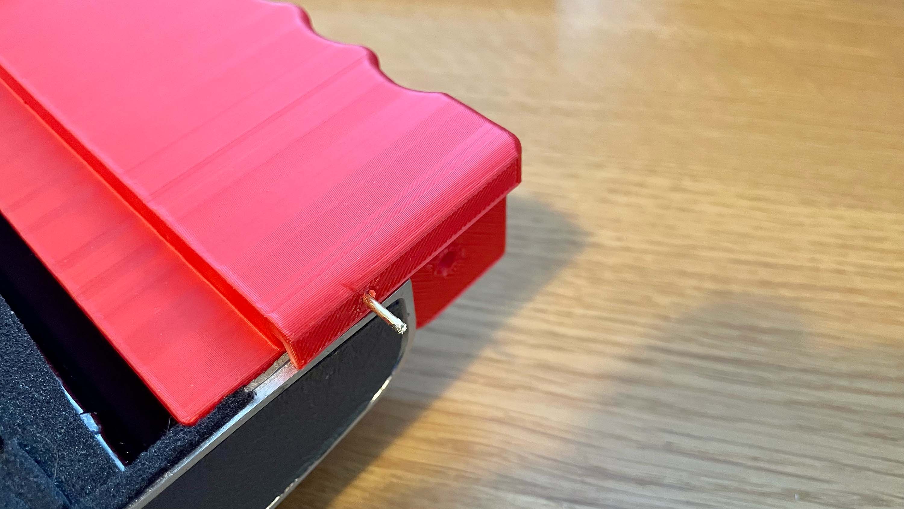
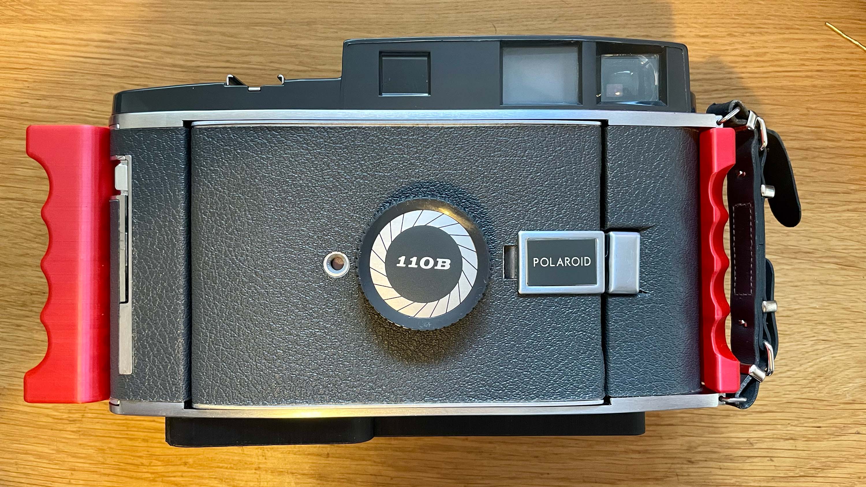
- Left-hand grip (3D-printed, optional, make sure you print the right one for your specific model)
- Right-hand grip (3D-printed, optional, make sure you print the right one for your specific model)
- Double cold-shoe adapter (3D-printed, optional, just 110b for now)
- Door pin and spring shim (3D-printed, only if you’re converting a 110a)
- A sheet of light-sealing foam to cut to size
- 1/4-20 tripod screw with length 16mm (excluding head)
- 1/4-20 tripod screw with length 11mm (excluding head)
- 3/8-16 male to 1/4-20 thread apapter - Google for SmallRig 1610 (optional, only if you print the adapter for use with a tripod)
- An empty Instax wide cartridge
- Either ground glass, a perspex sheet, or just the lid off a takeaway curry container cut to size (I used the lid approach)
The conversion
Step one: print your parts
This one’s optional, as you may opt to order these from a 3D printing company instead, but I think it’s pretty important that I at least provide the settings used to get results that I was happy with (after many tries).
Click here to download the necessary files from Thingiverse or download them directly.
I used a Creality Ender 3 v2, which is an incredible machine for the price. Cura slicer was used to slice my STL files to G-code. All the models are in the recommended orientation for printing already. Your temperatures will vary depending on the material you choose to print with, but I think these settings will help you get results that are both pretty and strong (it takes forever to print, though, so tweak until it suits your needs):
- Layer height: 0.16mm
- Wall thickness: 1.2mm
- Wall line count: 3
- Top/bottom thickness: 0.84mm
- Infill density: 20%
- Enable print cooling: Yes
- Fan speed: 100%
- Initial fan speed: 0%
- Regular fan speed at height: 0.8mm
- Generate support: Yes
- Support placement: Everywhere
- Support type: Line
- Support density: 10%
- Build plate adhesion type: Raft
I used a brand of filament from Amazon called “Eryone”, and decided on the “Jet Black” colour for the bracket, and red for the grips and inifinity stop. I set the hot-end to 200 degrees celsius, and my bed starts out at 60 for the initial layer, then eases down to 50 degrees celsius for the rest.
Step two: remove the back door(s) and film holder
Both the rear door and inner door are held in place with a thin rod threaded through the hinge. Getting it out is as easy as poking the smallest screwdriver (or even better, a pick) that fits into the topmost hole of the hinge. If you’re lucky, you should just be able to push out the rod, grab it from the bottom with a pair of pliers, and pull it all the way out. If not, you’ll need to gently tap the top of your screwdriver (or pick) with a hammer until it peeks out. Do this with the rear door first, then the inner door, and set them aside (or toss them in the trash as you won’t be needing them again). Keep the rods, you’ll need both of them if you decide to use the grips.
Next, inside the camera on the left is a piece of plastic that was used to hold the original Polaroid roll film. It has two small screws. Unscrew them, remove the plastic piece, and replace the screws for light-tightness (and aesthetics).
For the 110a the lens door pin and spring sits behind this plastic piece. Be careful when removing it as the spring will shoot out and be lost to time. Once you’ve removed the plastic and collected the pin and spring, place them back into the hole carefully, and hold them in place by screwing the 3D-printed shim into the holes that were holding the plastic piece.
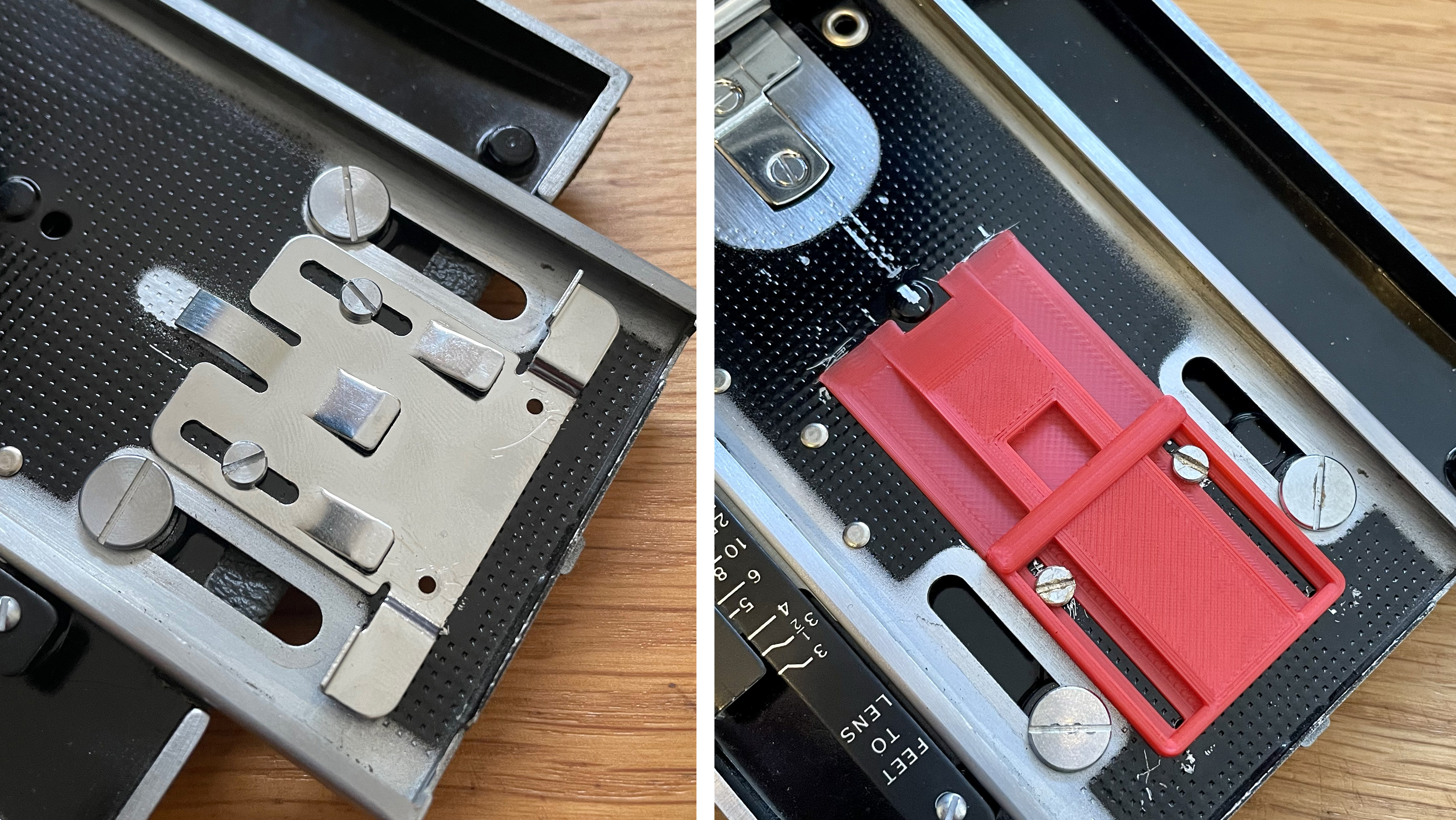
Step three: bend some tabs down, have at the bottom lip, and get out the Dremel
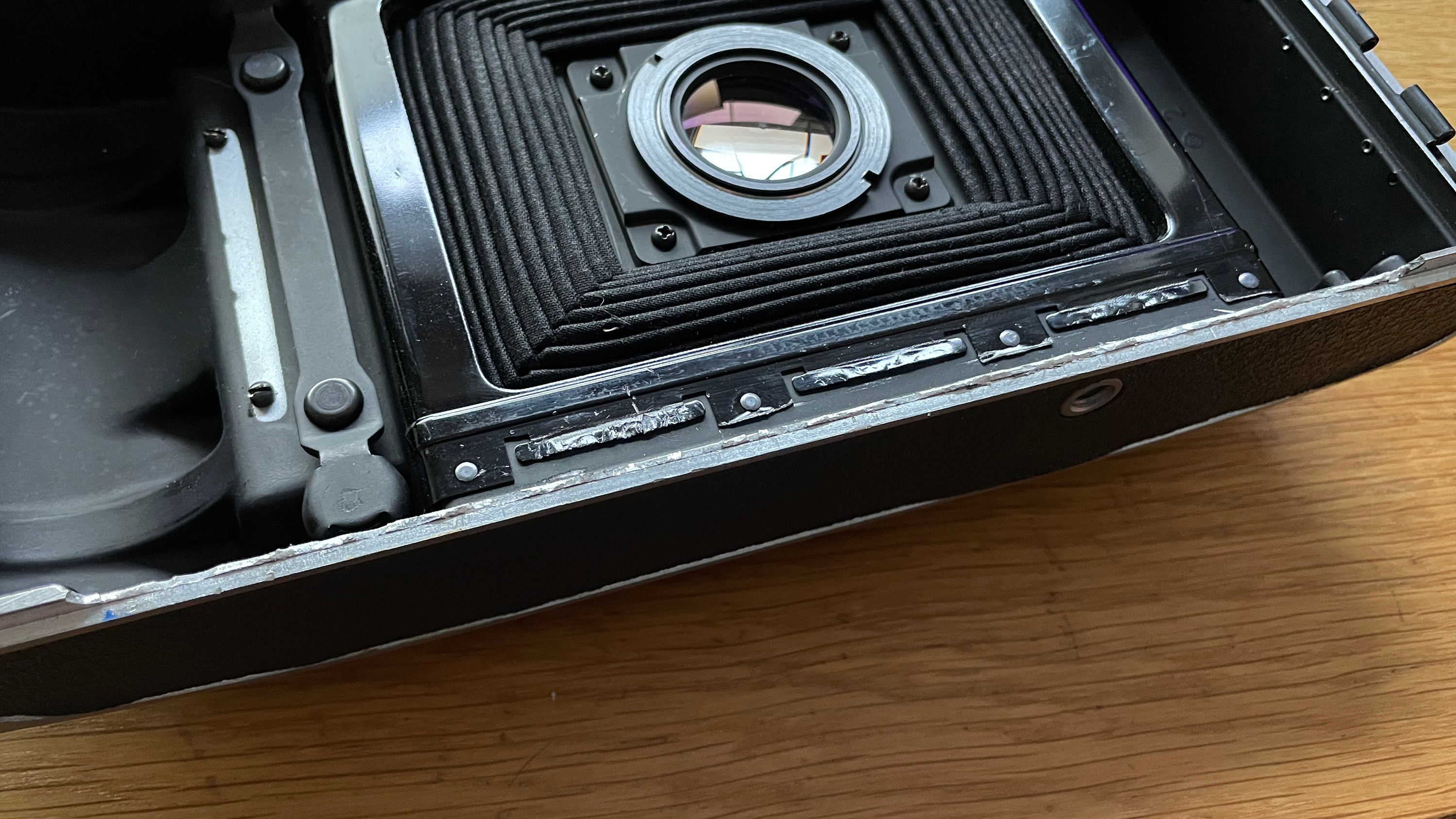
All around the film gate you’ll see thin metal tabs standing up. These will prevent the Lomograflok from sitting flush. I just bent them down, but if you wiggle them back and forth they’ll just snap off quite cleanly. Cut some light-sealing foam to size, and align it along all four sides of the film gate. This gives you some extra light-tightness and gives the Lomograflok a bit of cushioning.
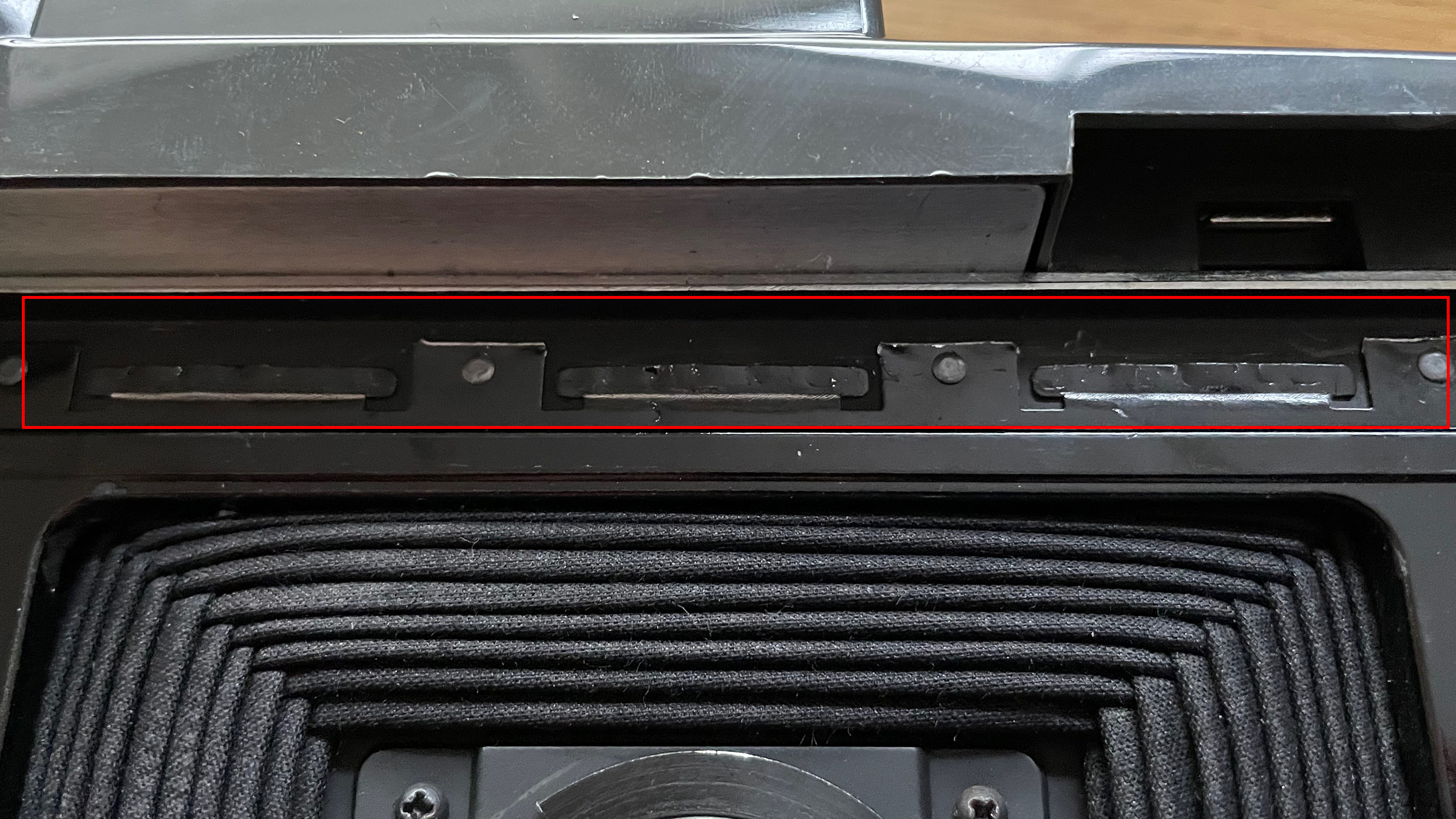
For the 110a there is a continuous metal strip at the top and bottom edge of the film gate, but no tabs at the sides. Just bend these back and flat.
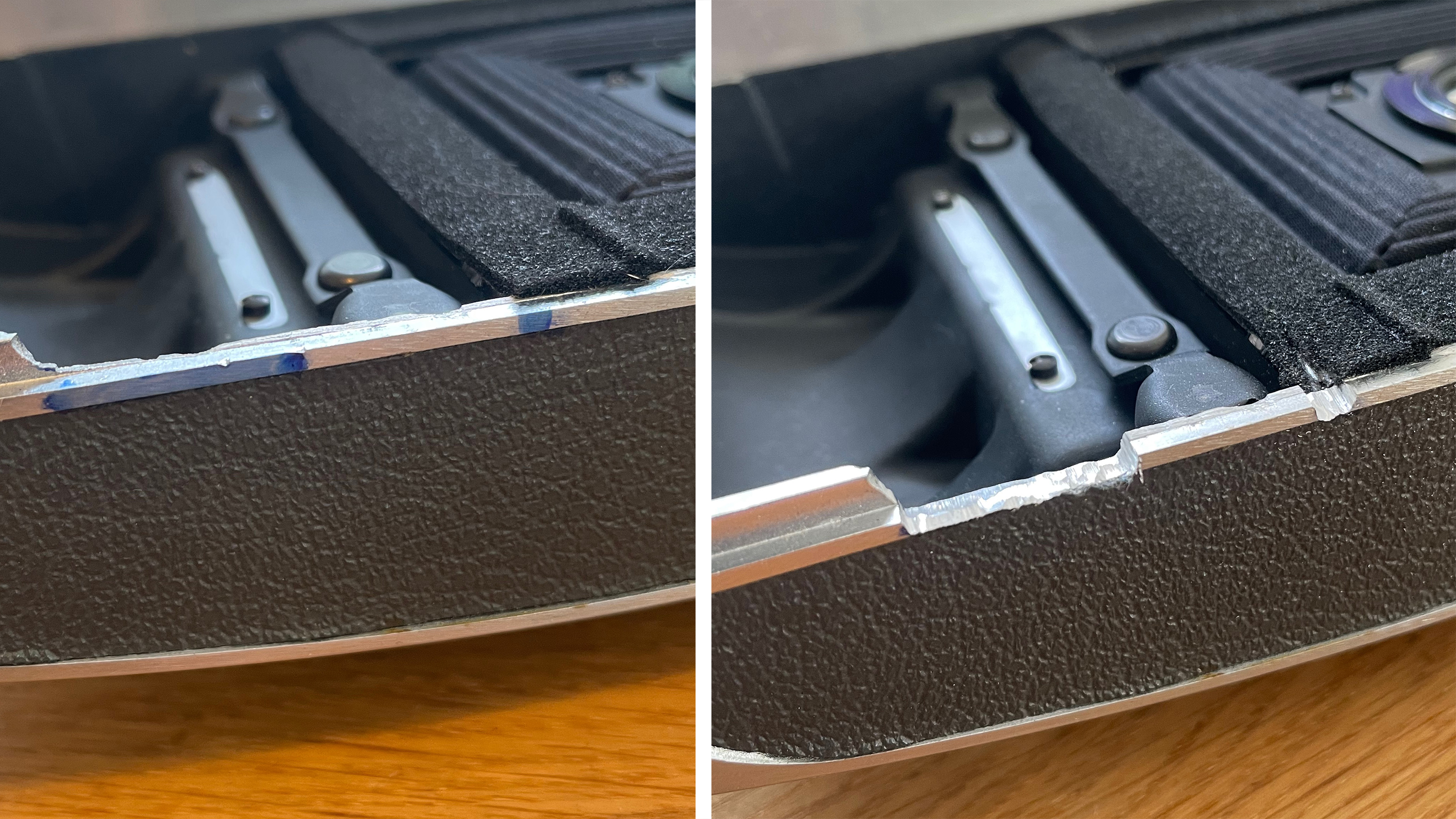
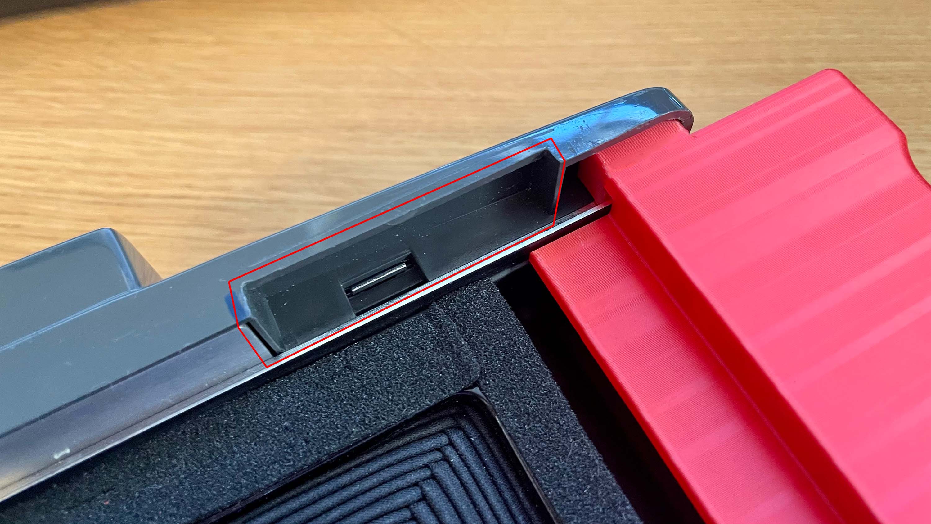
Next, you’ll need to measure where the Lomograflok sits when the camera’s film gate is aligned with the film plane. When you look at the top left of the camera you’ll see a little indentation. When the Lomograflok lies just to the right of this (on the inside of the top lip), it should perfectly align. Now mark the left and right edges of the Lomograflok on the bottom lip and add 2mm on either side. For me this ended up being ~21mm from the left, and ~5mm from the right.
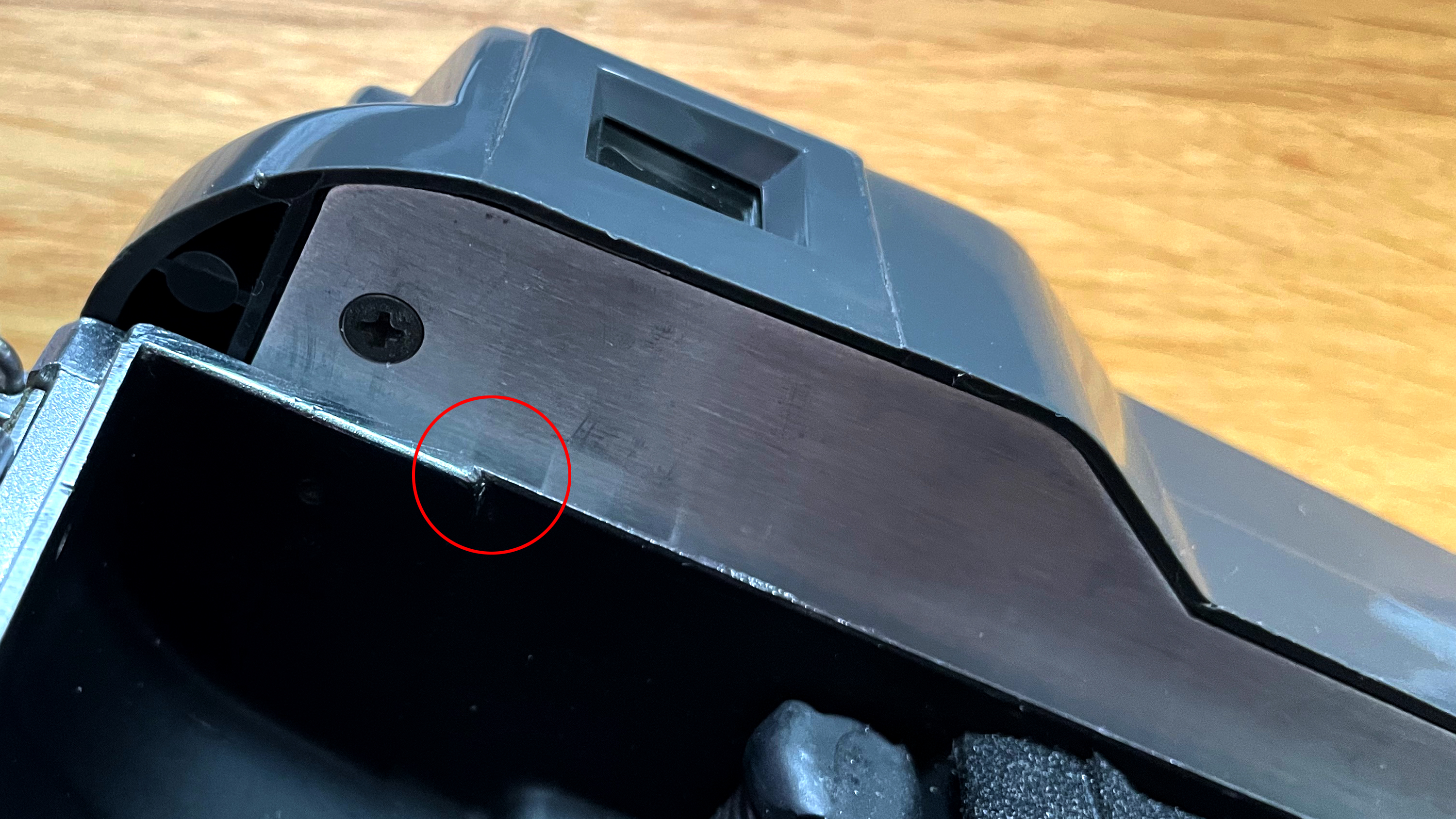
Now it’s time to get rid of the whole lip between these marks. Lucky for us it’s made of an extremely brittle metal, so all you need is a beefy pair of pliers. Grab the lip, bend outwards, and it should snap clean off. Repeat until you’re done. Then use a fine metal file to smooth it all out and tidy it up.
You’ll notice that the Lomograflok doesn’t sit flush yet. That’s because the Graflok mount “standard” requires two ridges for alignment, and that means we need to add indentations to match these. There’s a wide one (19.5mm) on the left edge, then a space (18.5mm), followed by a thin one (2mm). I marked them out and then (carefully) went at the body with a Dremel (a coarse metal file will do, but will take much longer), until the Lomograflok sat flush. Remember to use a fine file to get the new indentations down smooth as well.
To finish this part off, I used some extra light-sealing foam cut to size along the modified bottom edge to give a bit of protection to the soft plastic of the Lomograflok.
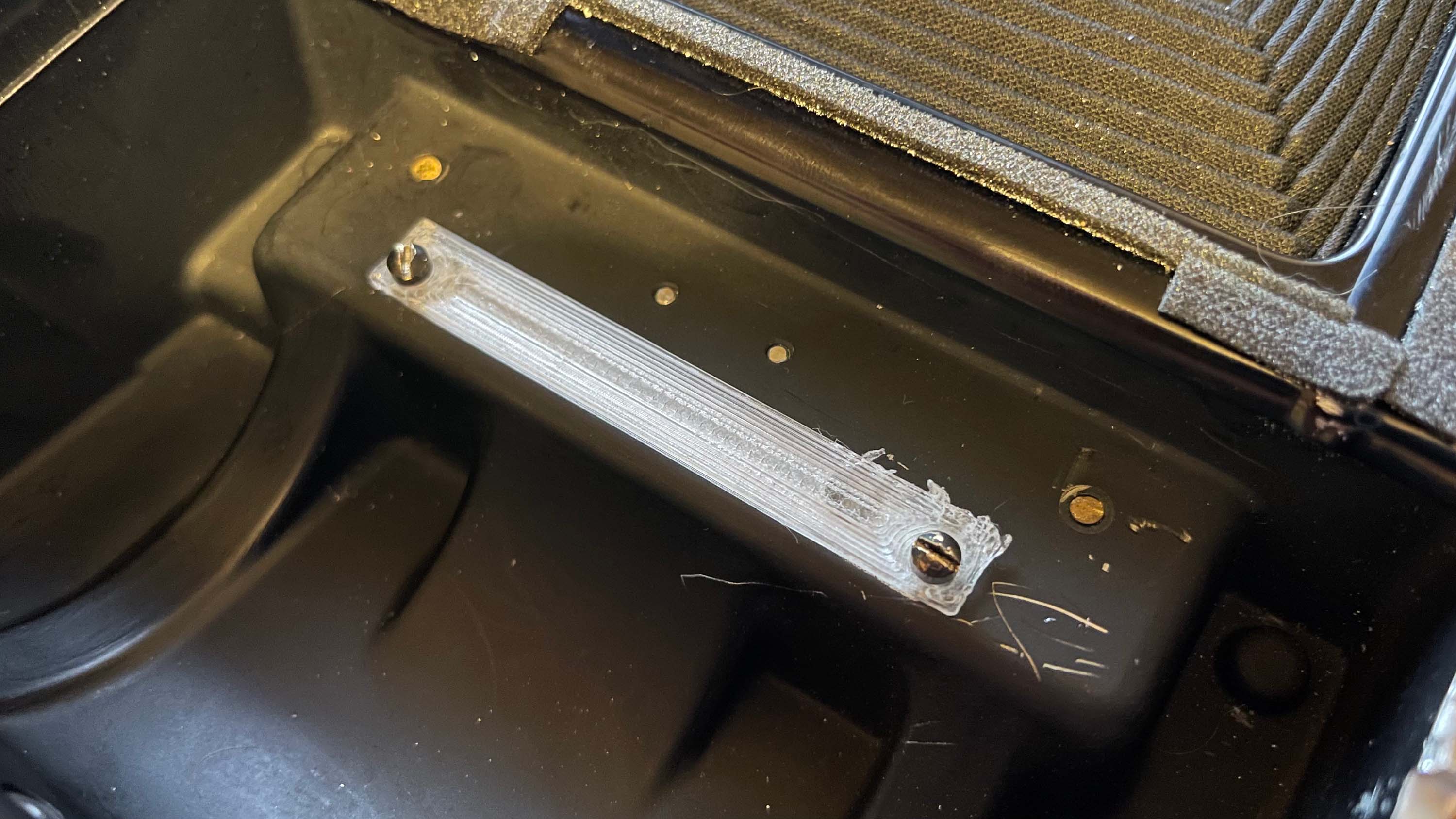
Step four: mount the new infinity stop
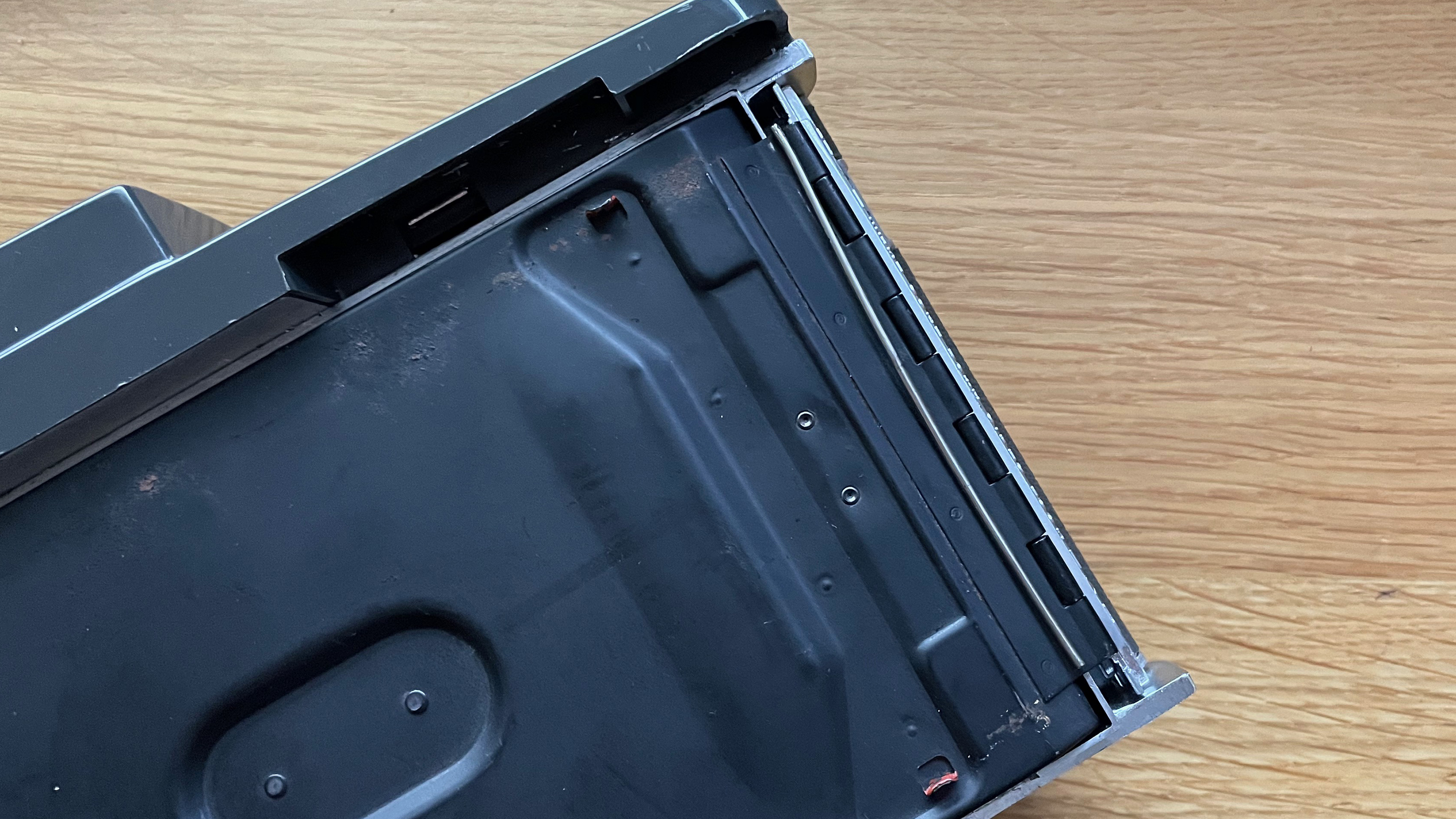
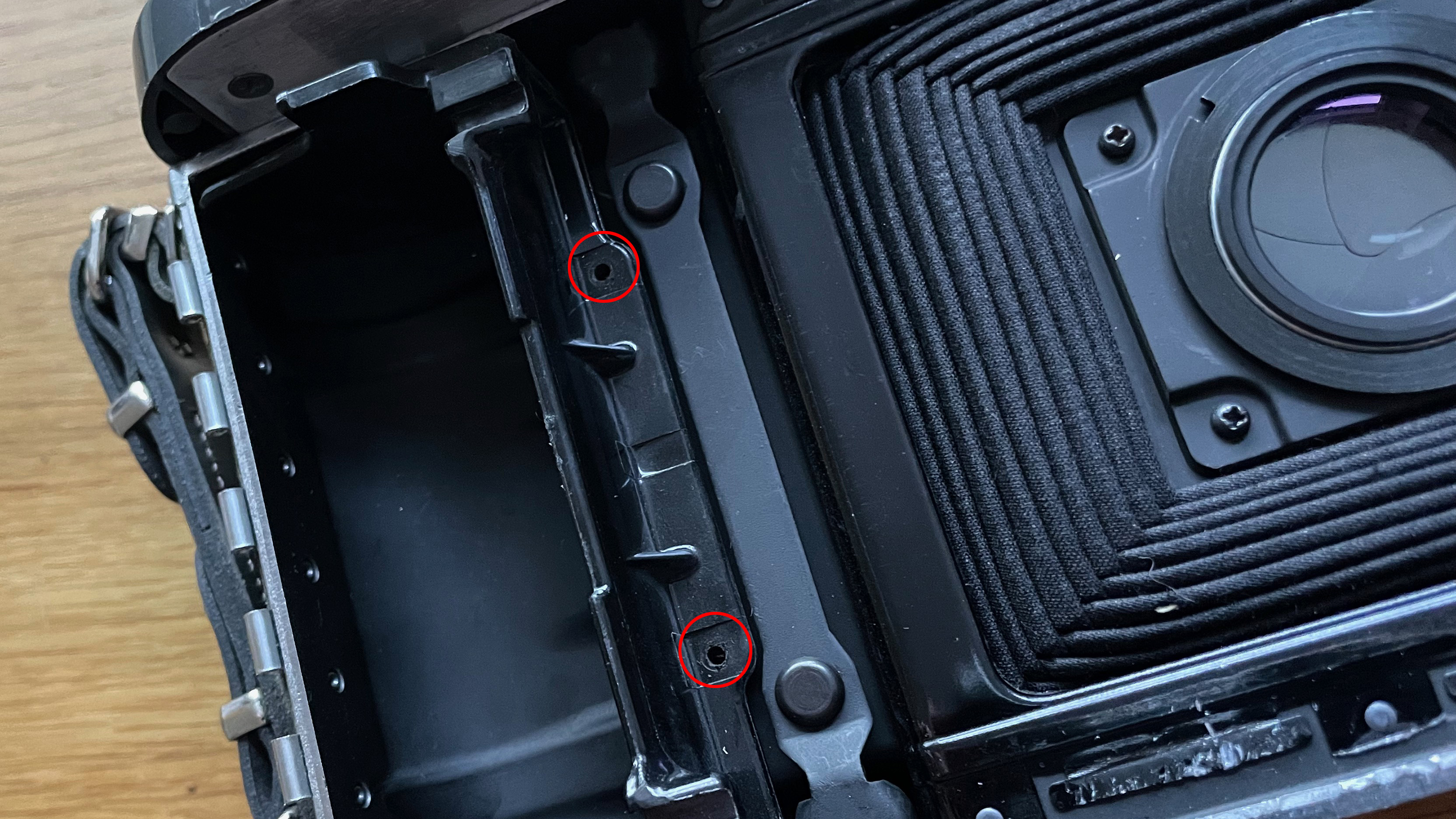
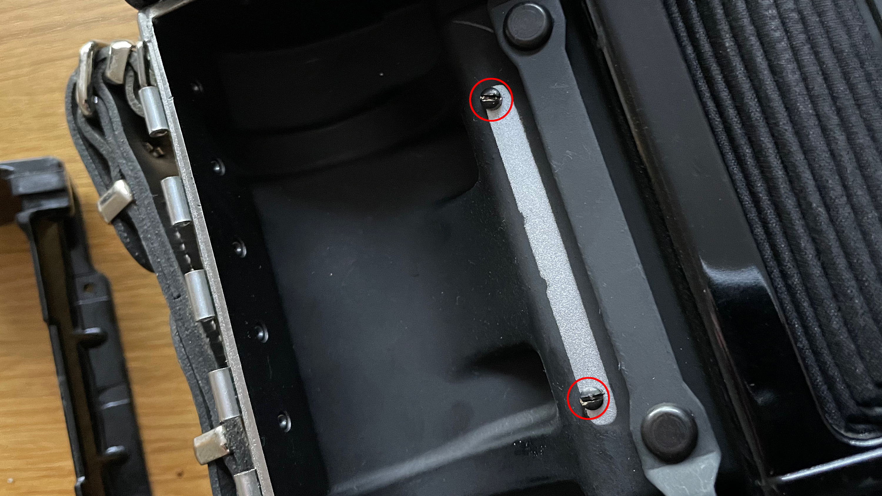
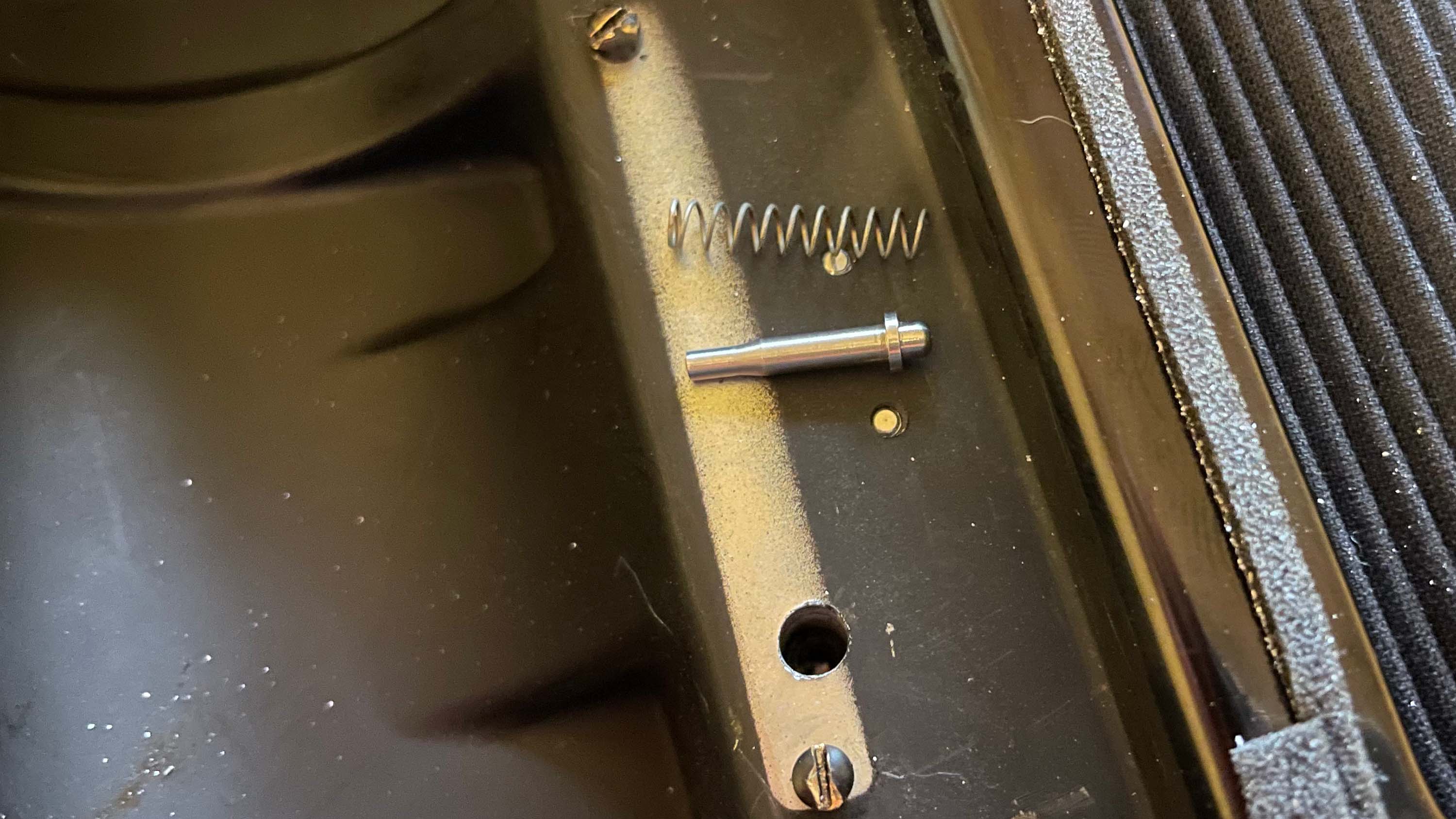
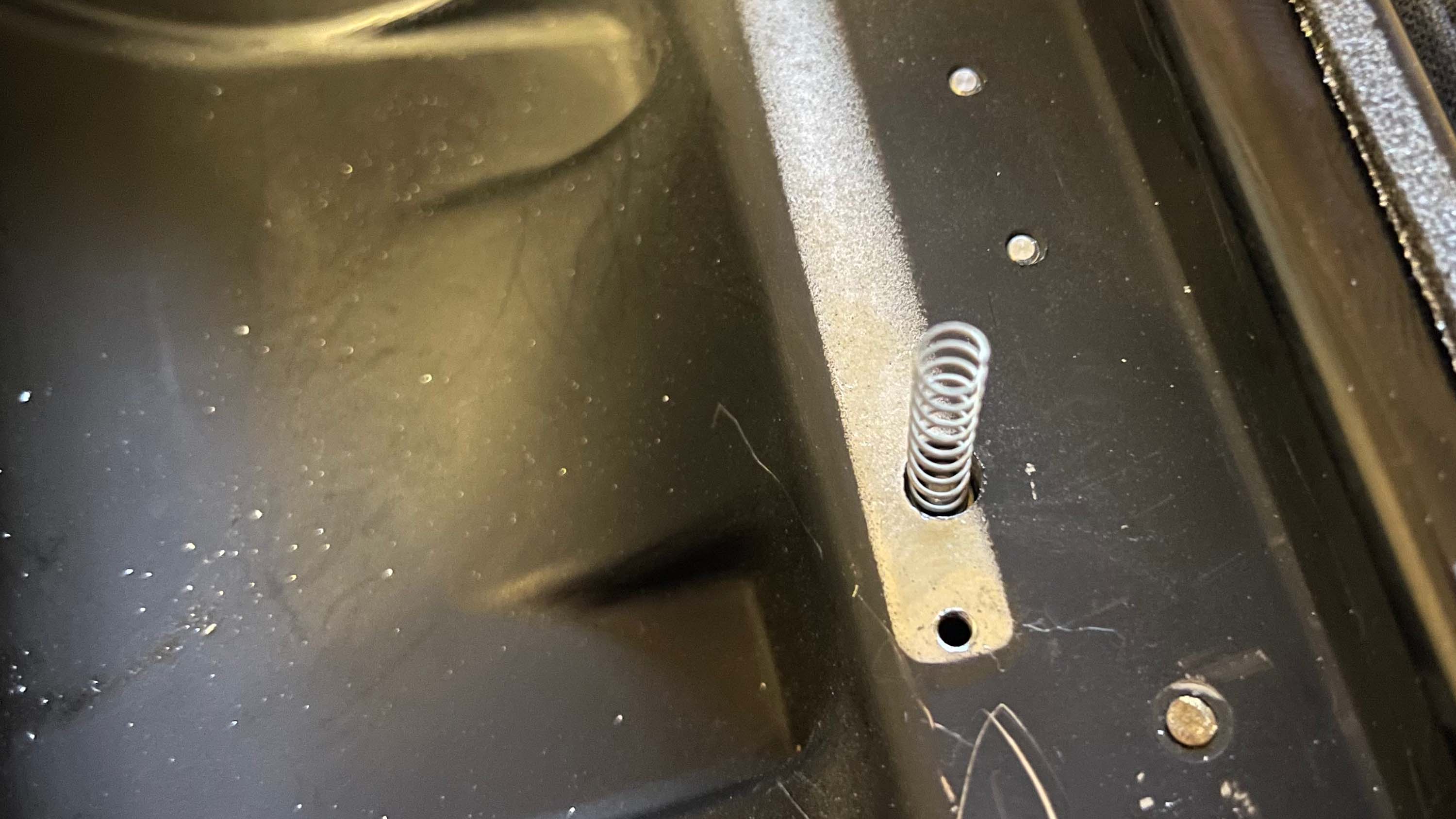
This conversion moves the film plane back by quite a bit, so we need to reset infinity. The existing infinity stop is locked into position by two rivets. You’ll need to drill these out from the back.
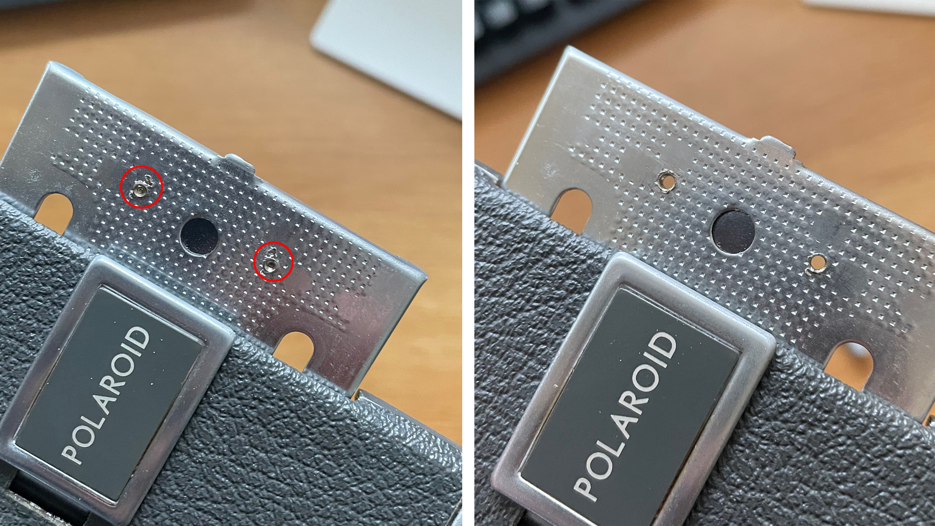
The existing infinity stop is unfortunately too short to do the job, so we need to replace it. Unscrew the infinity stop, keep both screws, and mount the new 3D printed infinity stop, screwing it in (but not too tightly yet).
Step five: Get the rangefinder cover off, ready for alignment
You’ll need to remove the rangefinder cover before you mount the Lomograflok, as it will be in the way if you need to make adjustments.
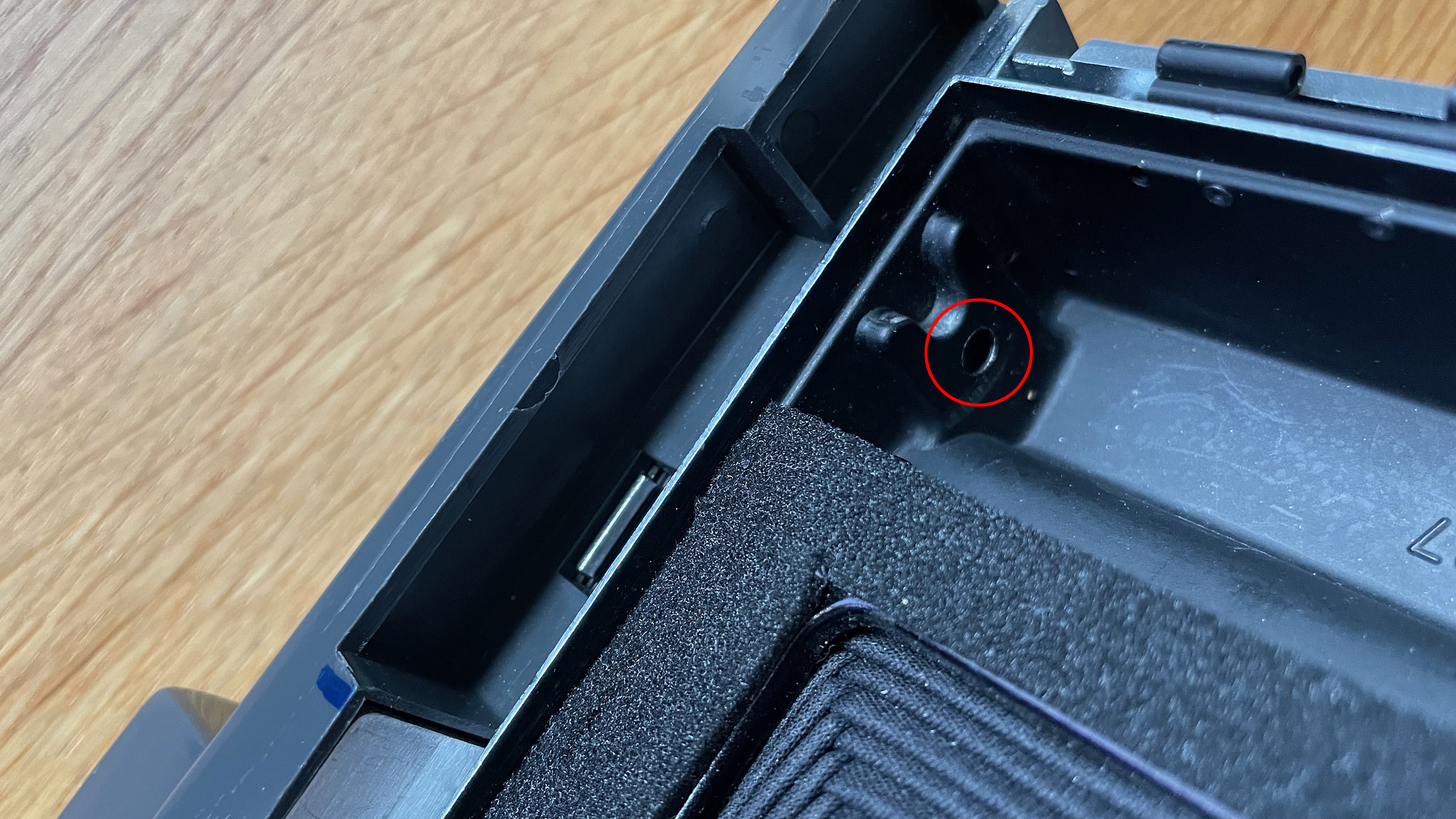
There are four screws that need to be removed (remember where each goes, they’re all different sizes):
- On the back, top left under the rangefinder, inside the camera body
- On the back, top right under the rangefinder, inside a little hole in the camera body
- On the top, right, the screw in the flash shoe (remember how it all fits together)
- On the front, with the bellows collapsed, slightly off center to the right, right under the rangefinder overhang
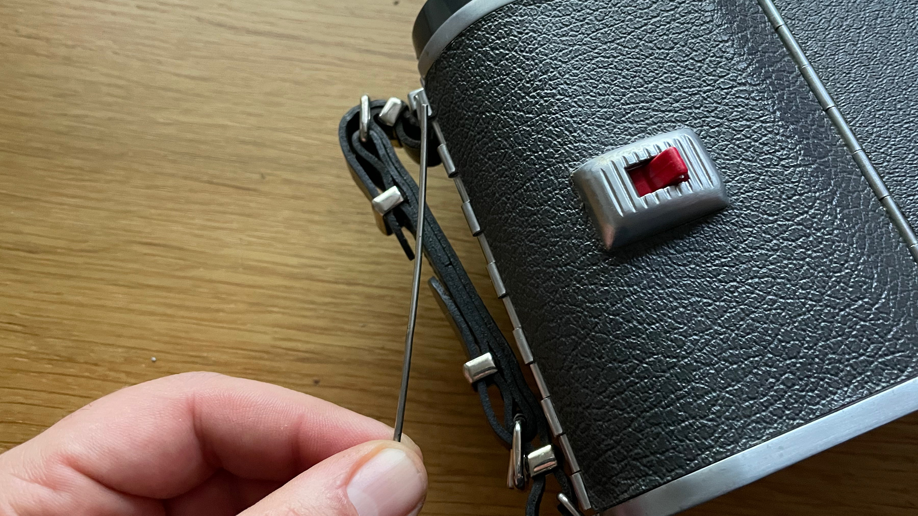
- For the 110a you need to remove the leather strap on the left-hand side as well
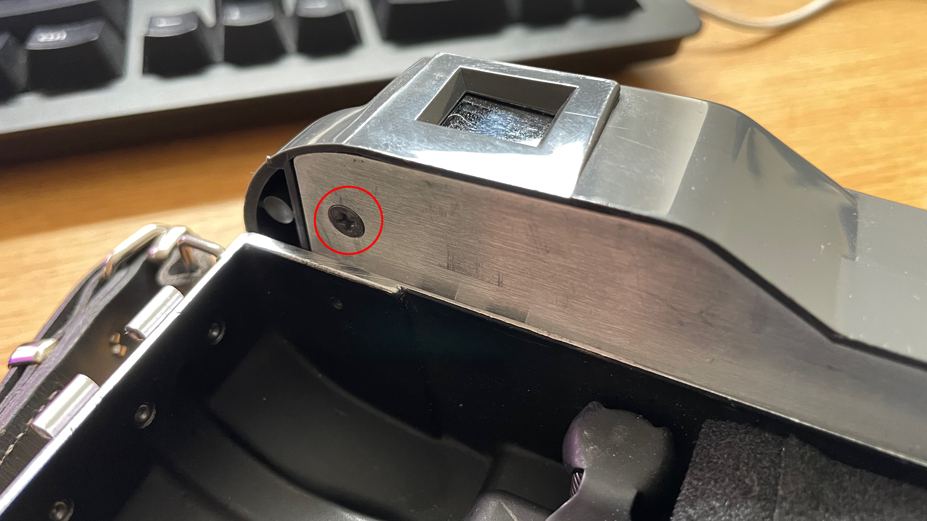
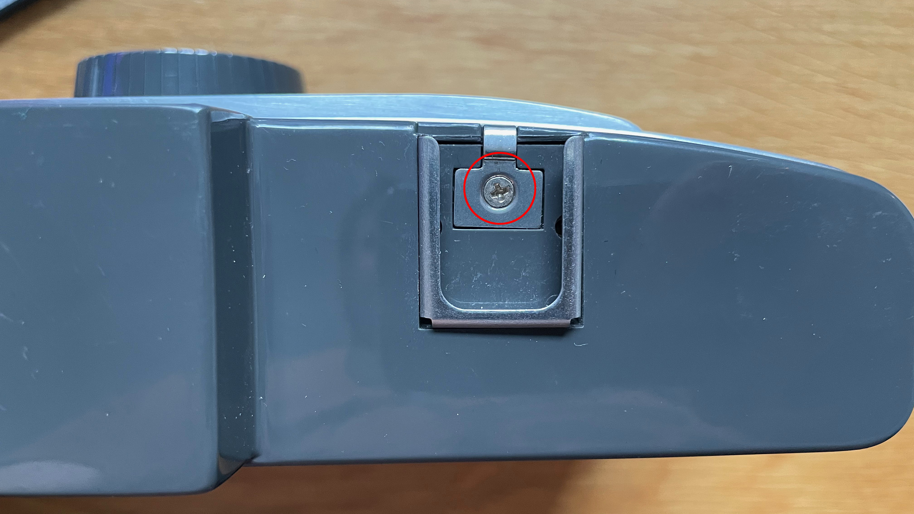
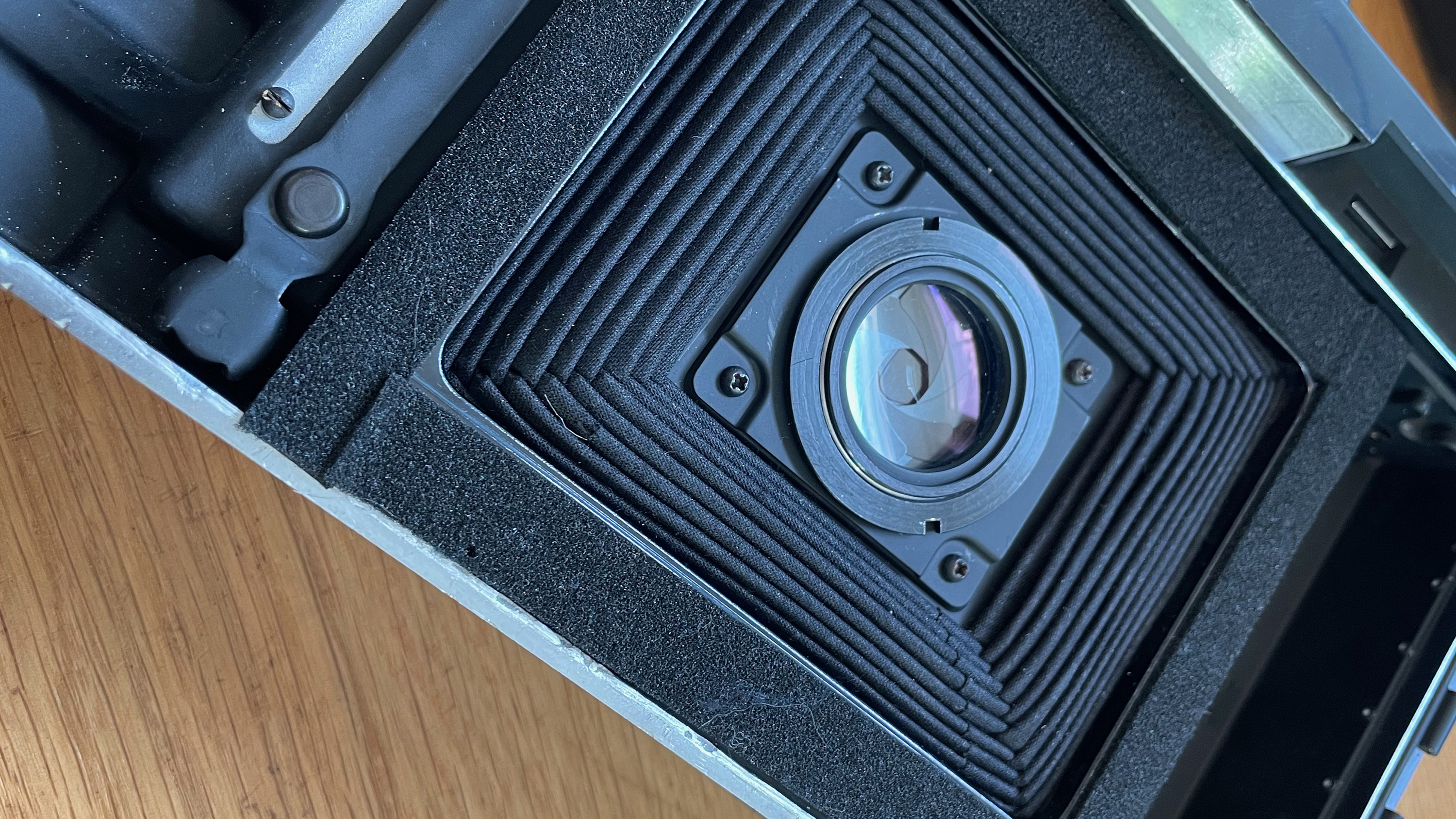
Be extremely careful when you lift off the plastic rangefinder cover. Some of the glass inserts might be loose, and the flash shoe’s wire is still attached. I cut the wire as it just gets in the way, the flash shoe is an unconventional size (and orientation), and I plan to design an adapter with new standard hot-shoe which will be soldered on later. I gave all glass surfaces a good clean with some residual oil remover, both those in the cover, and the rangefinder mechanism. It can make an incredible difference to the brightness of the viewfinder patch. Just be gentle as you don’t want to throw the alignment out if you can help it.
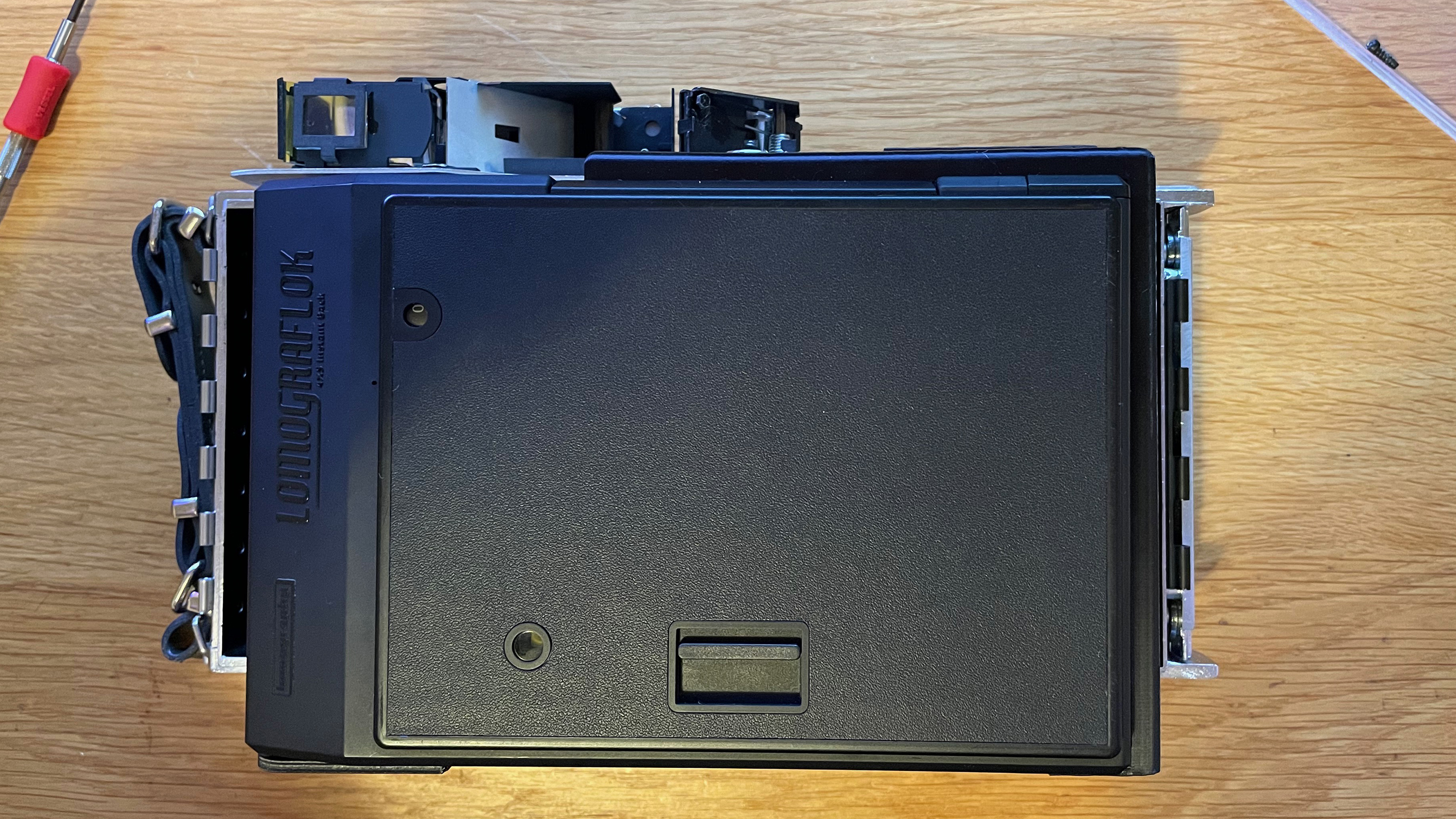
Step six: mount the Lomograflok to the Polaroid 110b for rangefinder adjustment
This part is easy. Before you start, remove the dark-slide. Then carefully slide your Lomograflok into the 3D printed bracket, with the buttons towards the open side. The short arm of the bracket should be on the bottom of the Lomograflok, and the tripod hole should roughly align with the hole in the bracket. Don’t worry if they don’t 100% align, when you screw things together, everything will be pulled into the correct position, so go ahead and screw the bracket to the Lomograflok using the shorter 1/4” tripod screw (don’t over-tighten).
Next, rest the Lomograflok and bracket just to the right of the indentation mentioned above, on the little ledge right below the top lip. Now roughly align the hole in the bottom of the bracket with the camera’s tripod hole and screw them together using the longer 1/4” screw. Once again, this should gently pull everything into the correct position. It should be secure, but still be careful with it as the top cover isn’t in place and it plays quite a big part in keeping things where they should be.
Step seven: infinity stop and rangefinder alignment
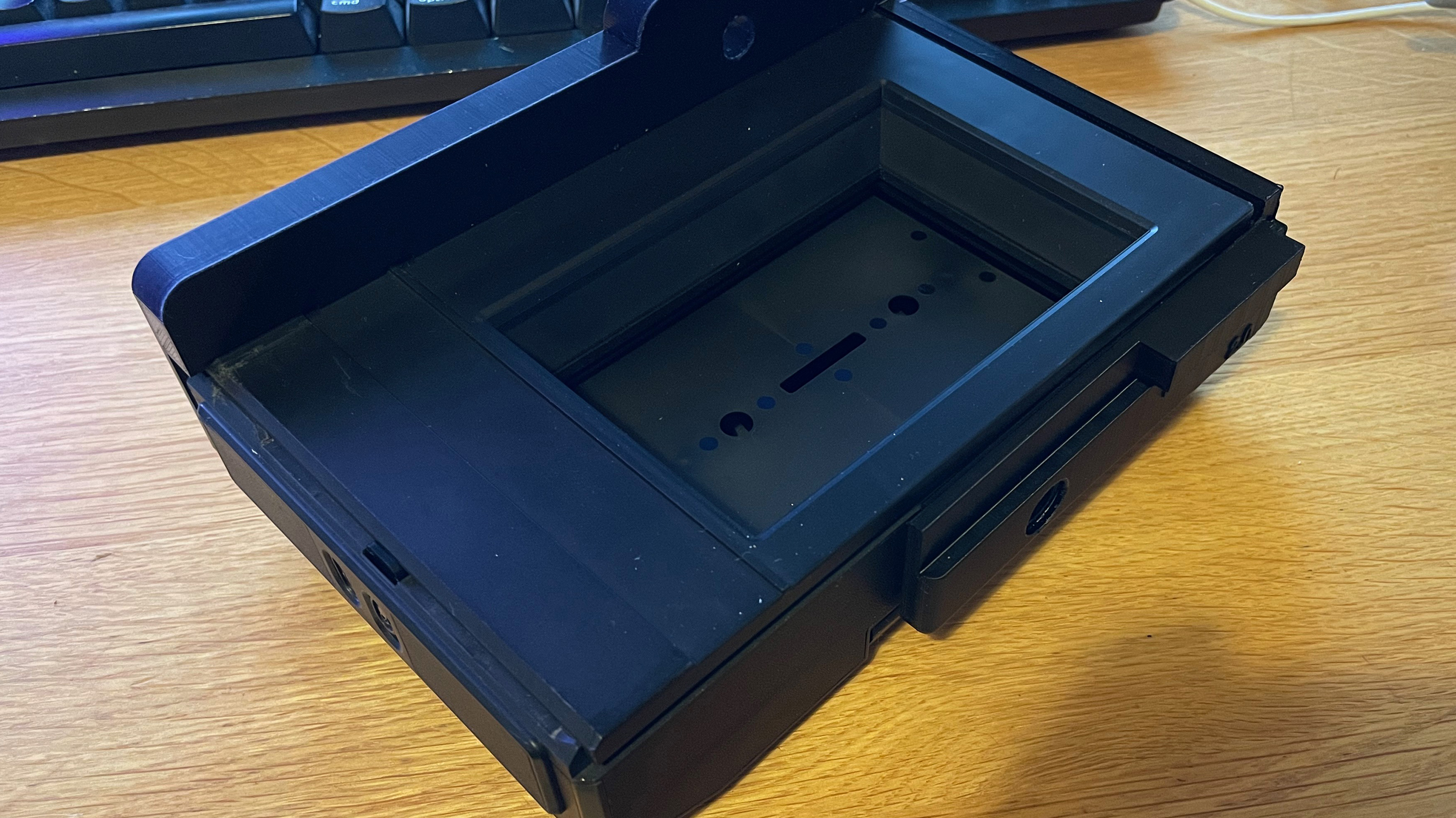
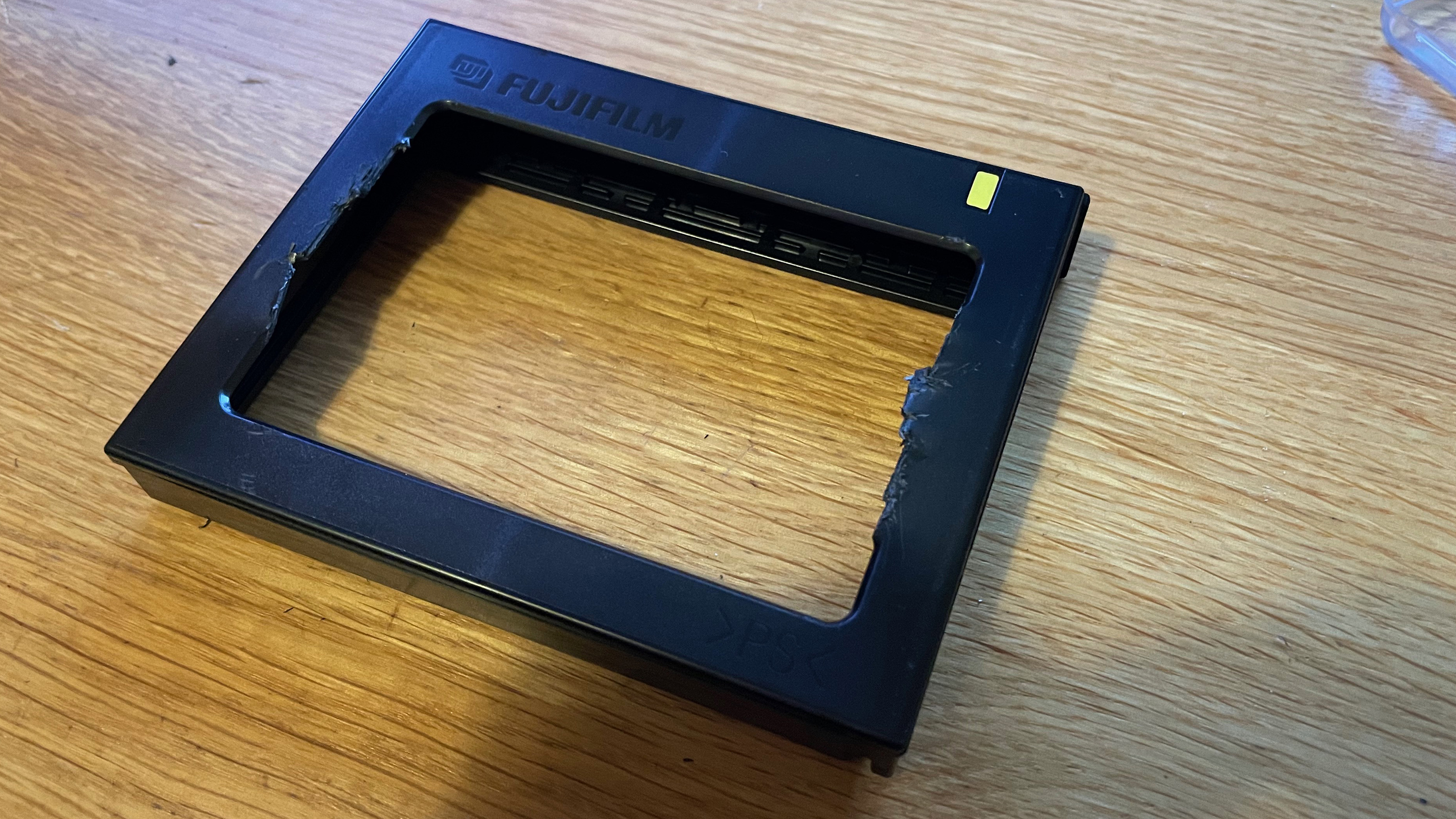
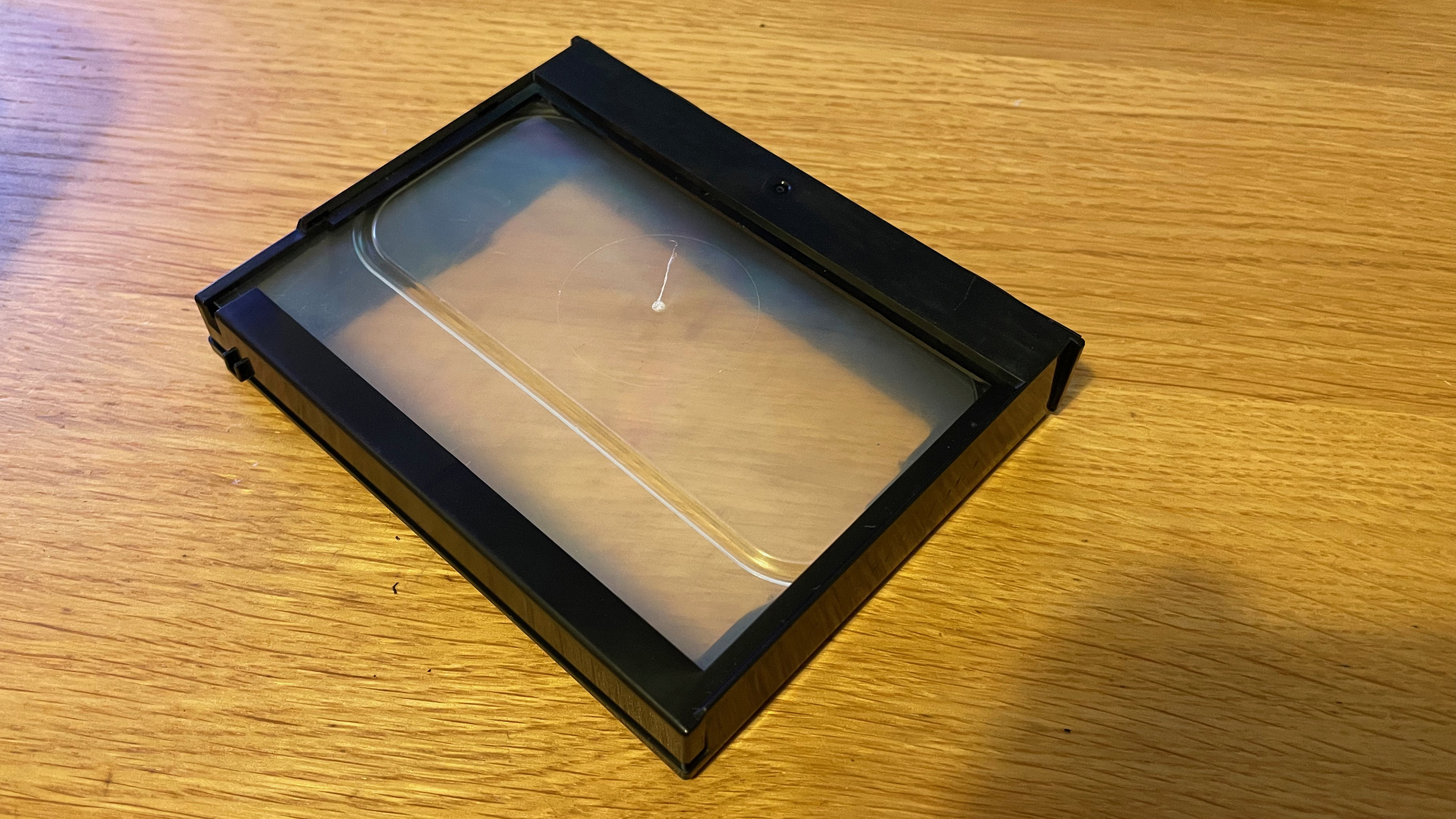
This is where things start getting exciting, but slightly frustrating. Take the empty Instax wide cartridge and cut out the strip of plastic running along the back, also removing the innards. Then tape your ground glass (or plastic takeout lid) to the inside front of the cartridge, and load this into the Lomograflok.
Expand the bellows and lock the lens into place, then focus to infinity and aperture wide open at f4.7. Use a cable release, put the shutter into bulb mode, and lock the release to keep it open. Aim the camera at something far away with contrast, like a telephone pole or tree with no leaves against a clear sky. With the rear door of the Lomograflok open, using the image projected on the ground glass, slide the infinity stop back and forth until you get a sharp image. This is your new infinity focus point. Screw that infinity stop down.
Now comes the frustrating part: close focus. We can’t mount the camera on a tripod, because we’re using all the tripod holes. This means it feels like you need three hands to get this done. I approached it with a lot of patience. Each person will probably do this part differently, but the concept stays the same.
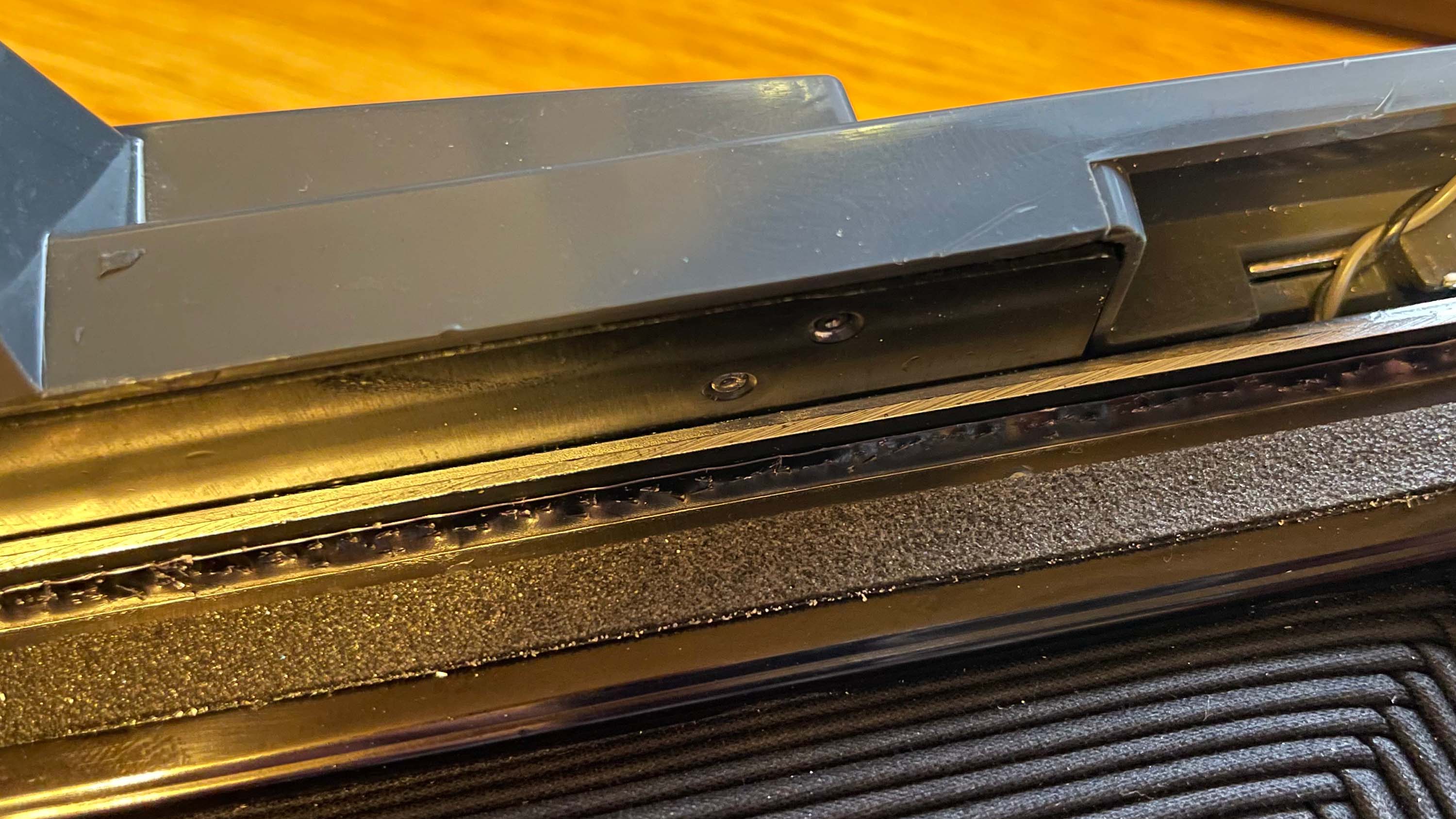
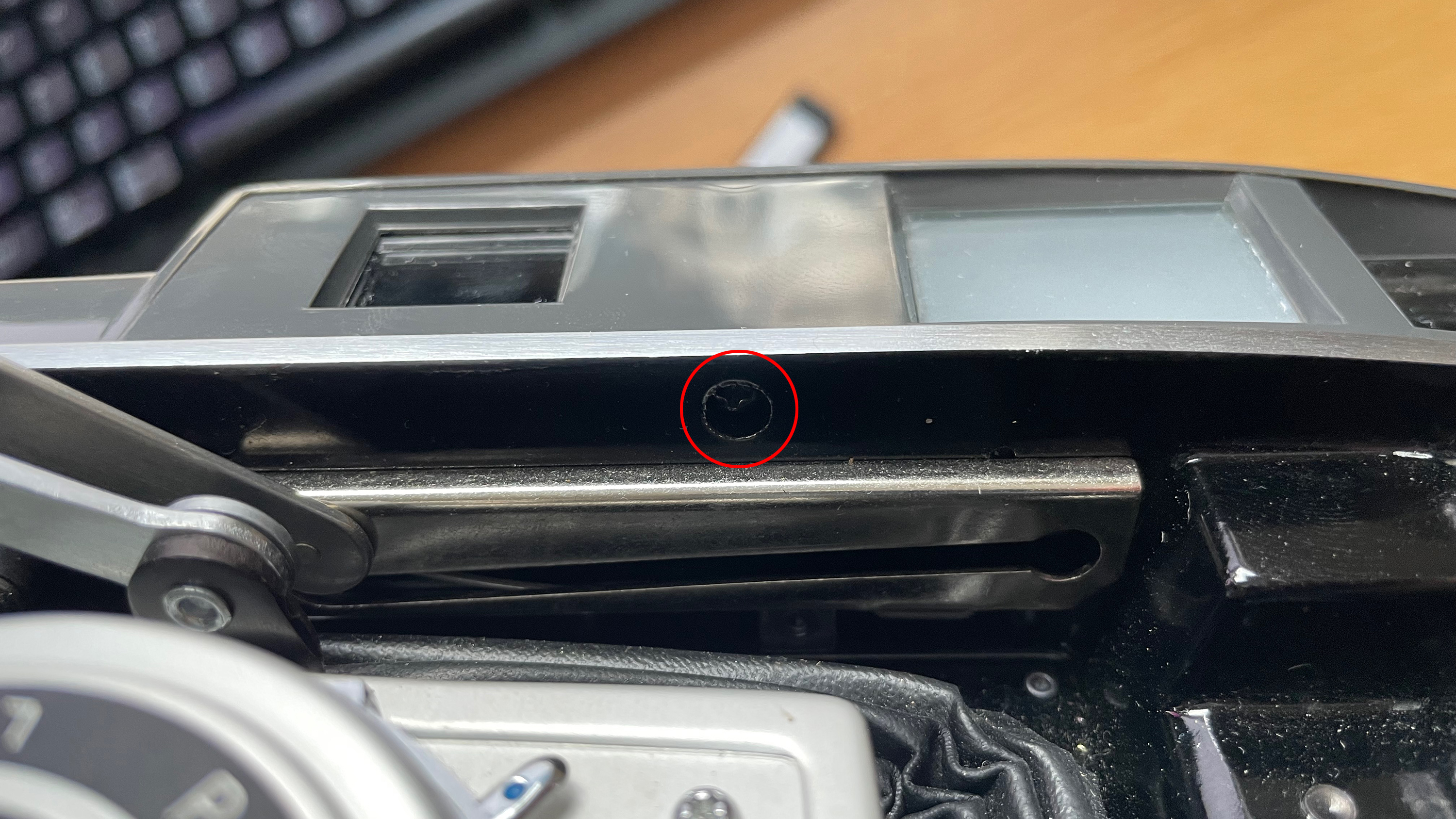
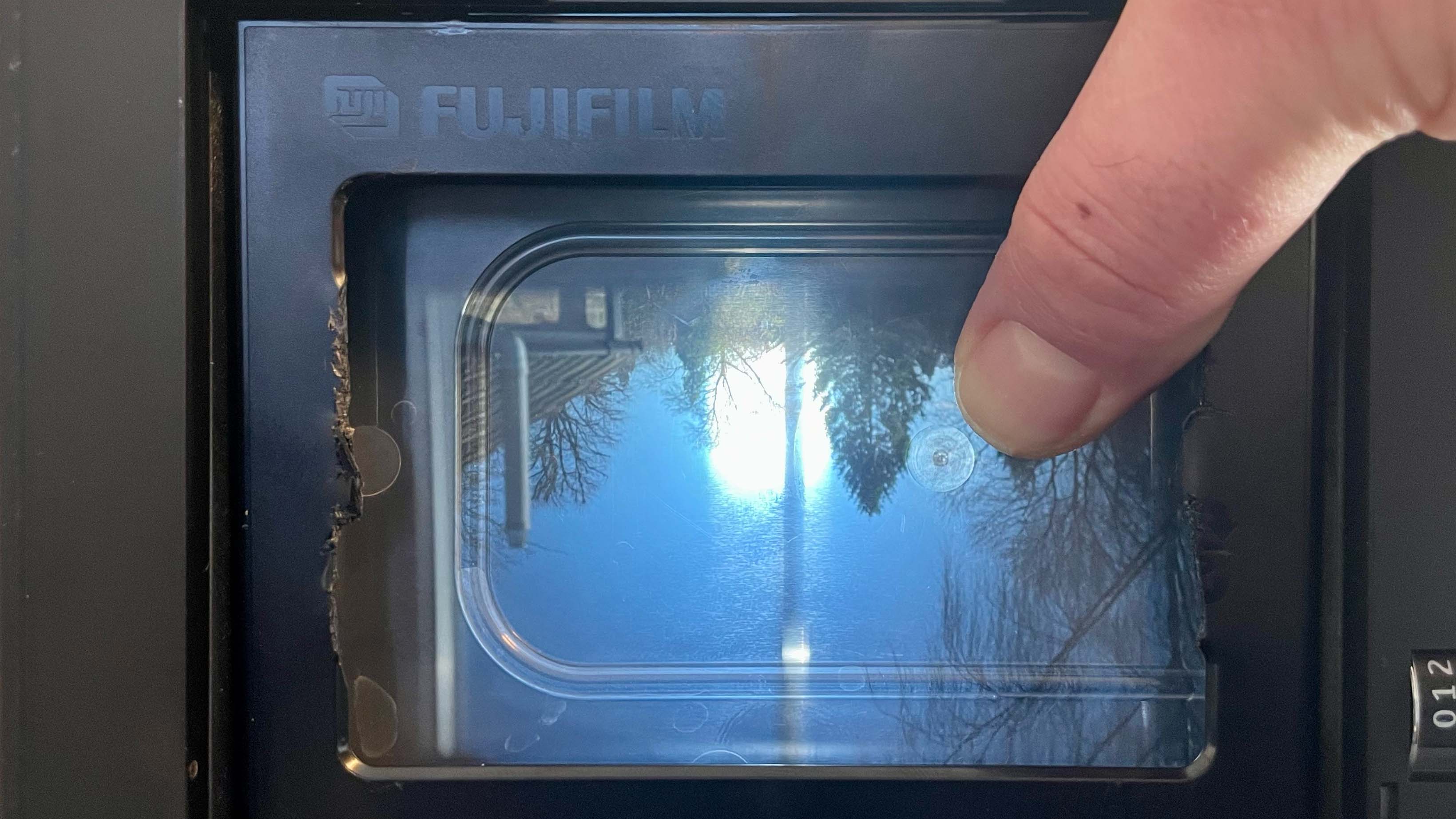
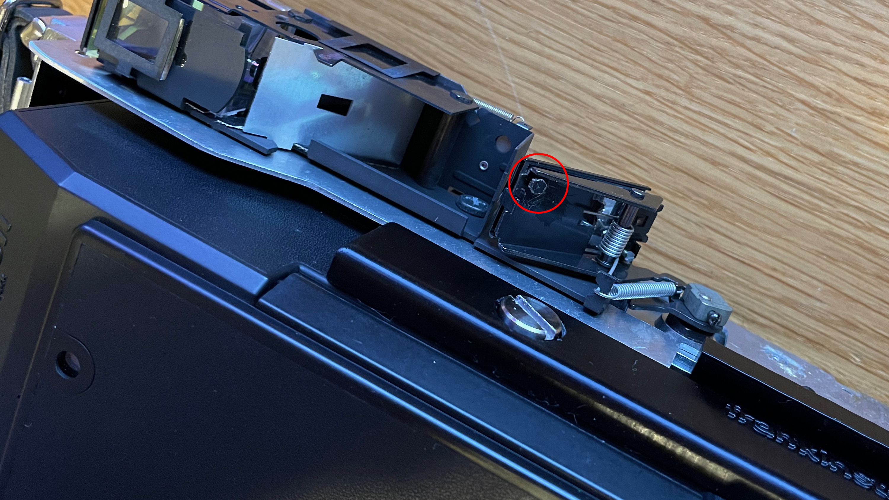
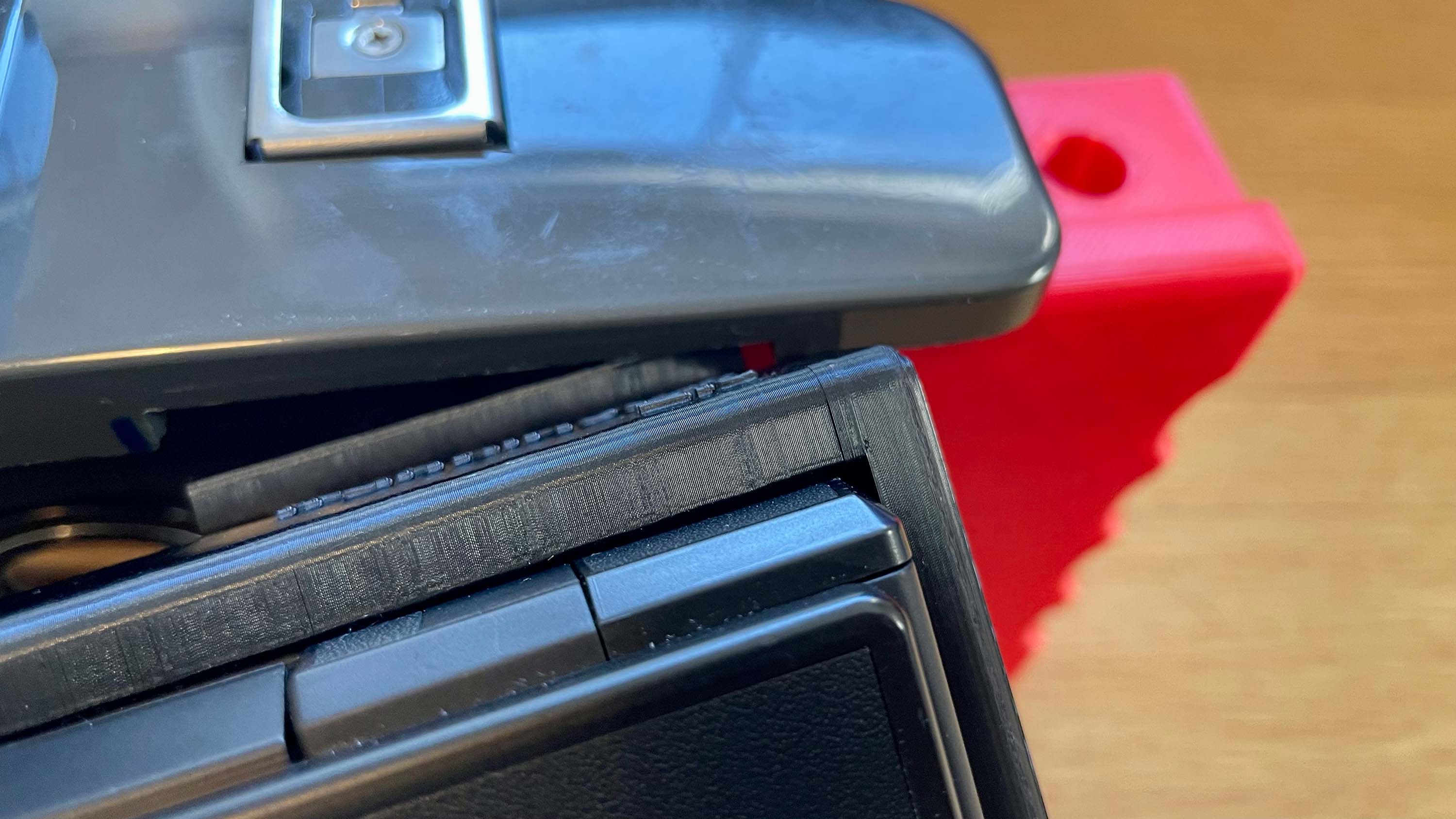
Anyway, I focus the lens to its closest distance: 3 feet. Then I place something like a magazine with contrasty text roughly 3 feet away. I move the camera back and forth while looking through the rangefinder until the patch aligns. Then I check the ground glass. Not in focus? Time to adjust the rangefinder. There’s a little screw (see image) on a slanted surface to the right of the rangefinder, on the back. If you’re lucky it’s a slotted screw. If you’re not (like me) then it’s a tiny hex bolt. Either way, extremely small movements of this screw will move your rangefinder patch left and right.
Now move your camera back and forth while looking at the ground glass until the image is in focus, check the rangefinder. If it’s not aligned, fiddle with the screw until it’s close. Rinse and repeat until the image on your ground glass and rangefinder agree.
Repeat this process for random distances between closest focus and infinity. Now go back to closest focus, as you’ll probably need to adjust it again, very slightly.
You might be lucky and have everything bang on without need to touch the rangefinder, but be prepared to have close focus accurately aligned, and infinity slightly off, as the distance between the lens and film plane has changed. This is a good trade-off for me as even though the rangefinder doesn’t agree, I know things are definitely in focus at infinity with a small enough aperture.
Step nine: Add the grips (optional)
If you had the patience to print the very intricate grips, fitting them is quite straightforward. I’d recommend threading the rod through the freshly printed grip hinges first to clear out any debris. You’ll need to fit the grips before the Lomograflok.
For both grips, press-fit the hinge into place. Then you’ll need to thread the rod through the hinge. Start from the bottom. I’ve found it can be a little tight, so make sure that everything is aligned, and push forcefully, but carefully. I use the pliers to help get some grip on the rod, and gently tap the last bit into place.

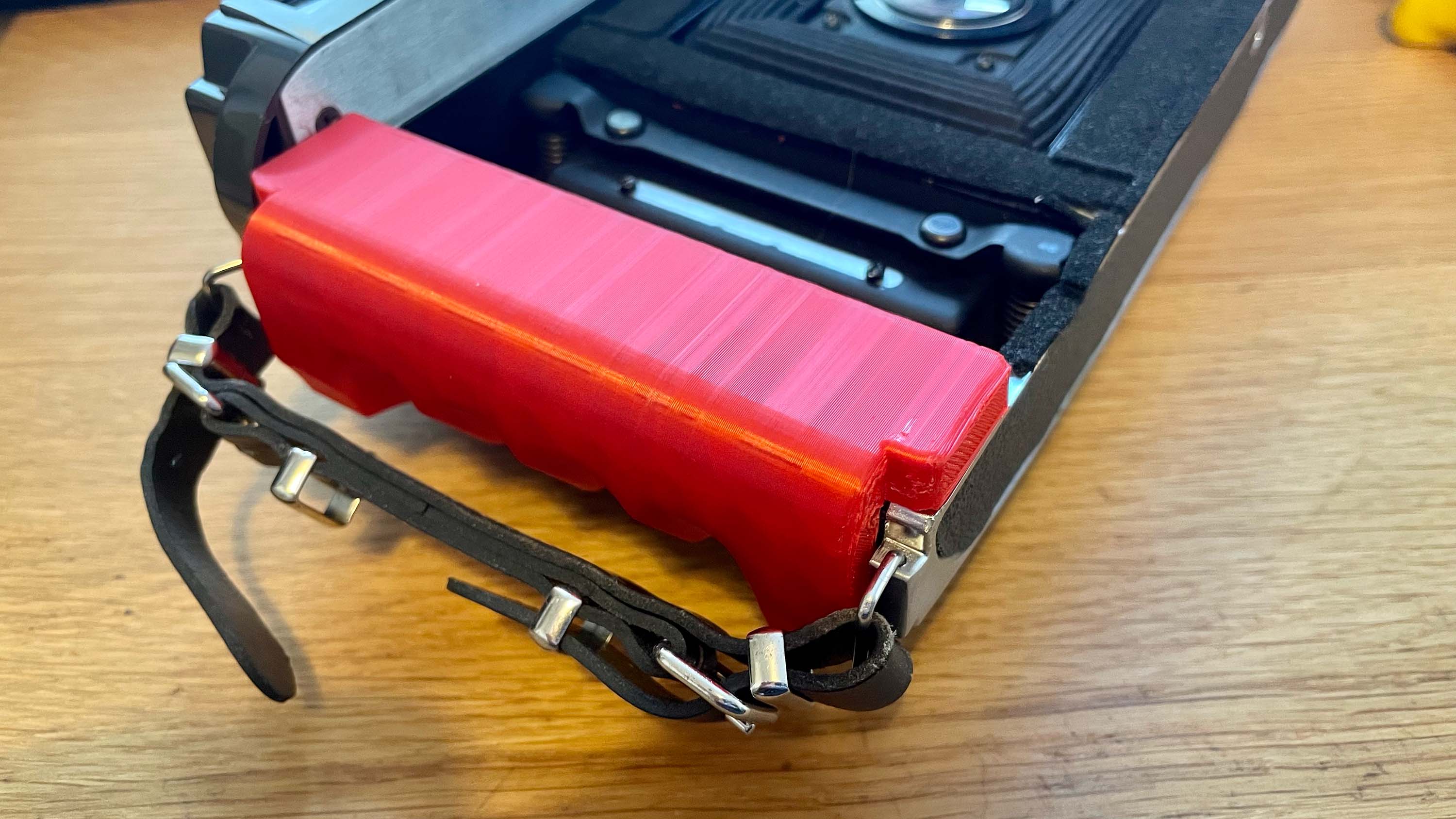
You’ll notice the right grip has a hole in it. This is to optionally fit a shutter release cable to move the shutter to a less awkward place. The trade-off here for the moment is that you’ll need attach/remove the cable release from the lens every time you collapse or open the camera.
Also note that, if you opt to use the grips, you won’t be able to use the Lomograflok’s darkslide, so remove that and put it somewhere safe.
There are specific grips for the 110b and 110a, so make sure you print the right ones. Unfortunately the bodies differ slightly.
Step nine: Wrap it up
Right, we’re almost done. Remove the bottom tripod screw and set the Lomograflok with the bracket still attached aside. Replace the rangefinder top cover and all four screws. If you’ve attached the right-side grip, take care to make sure that the little bit on the top fits into the top cover. You’ll see what I mean when you’re actually doing it.
Now you’ll need to take one extra thing into consideration when replacing the Lomograflok and bracket. You’ll notice there’s a gap in the rangefinder cover on the right, and a matching extrusion on the bracket. Tilt the Lomograflok and bracket slightly so that this extrusion slots into the hole inside the cover. This is an extra measure to keep the bracket securely in place.
If you printed the adapter for use with a tripod you’ll need to screw the 3/8-16 male to 1/4-20 female adapter into the relevant hole.
Now continue mounting the Lomograflok and bracket as you did before, securing it with the tripod screw. If you would like to mount a flash (with sync cable to the lens) and/or a light-meter, you can also optionally mount the cold-shoe adapter.
Finally, step ten: Get out there and shoot a test pack of film!
You’re good to go! Put in a pack of Instax wide, eject the pack’s dark-slide, and take your first picture. You might find that you need to continue tweaking your rangefinder. It’s all part of the fun.
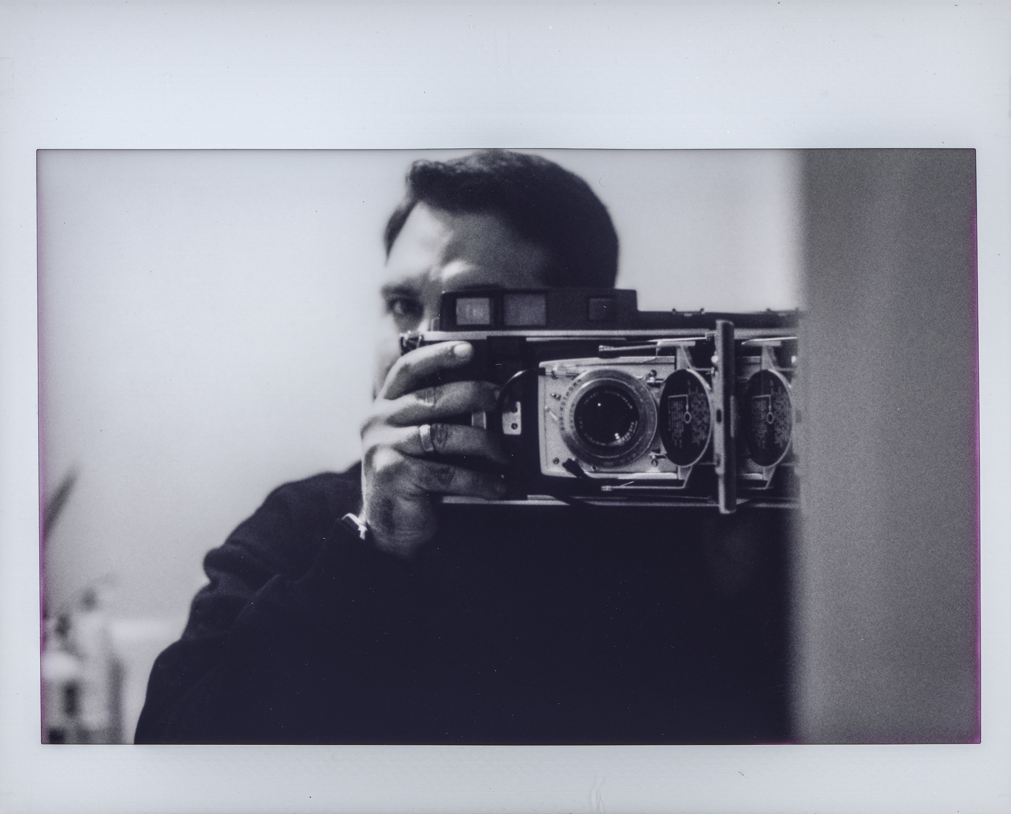
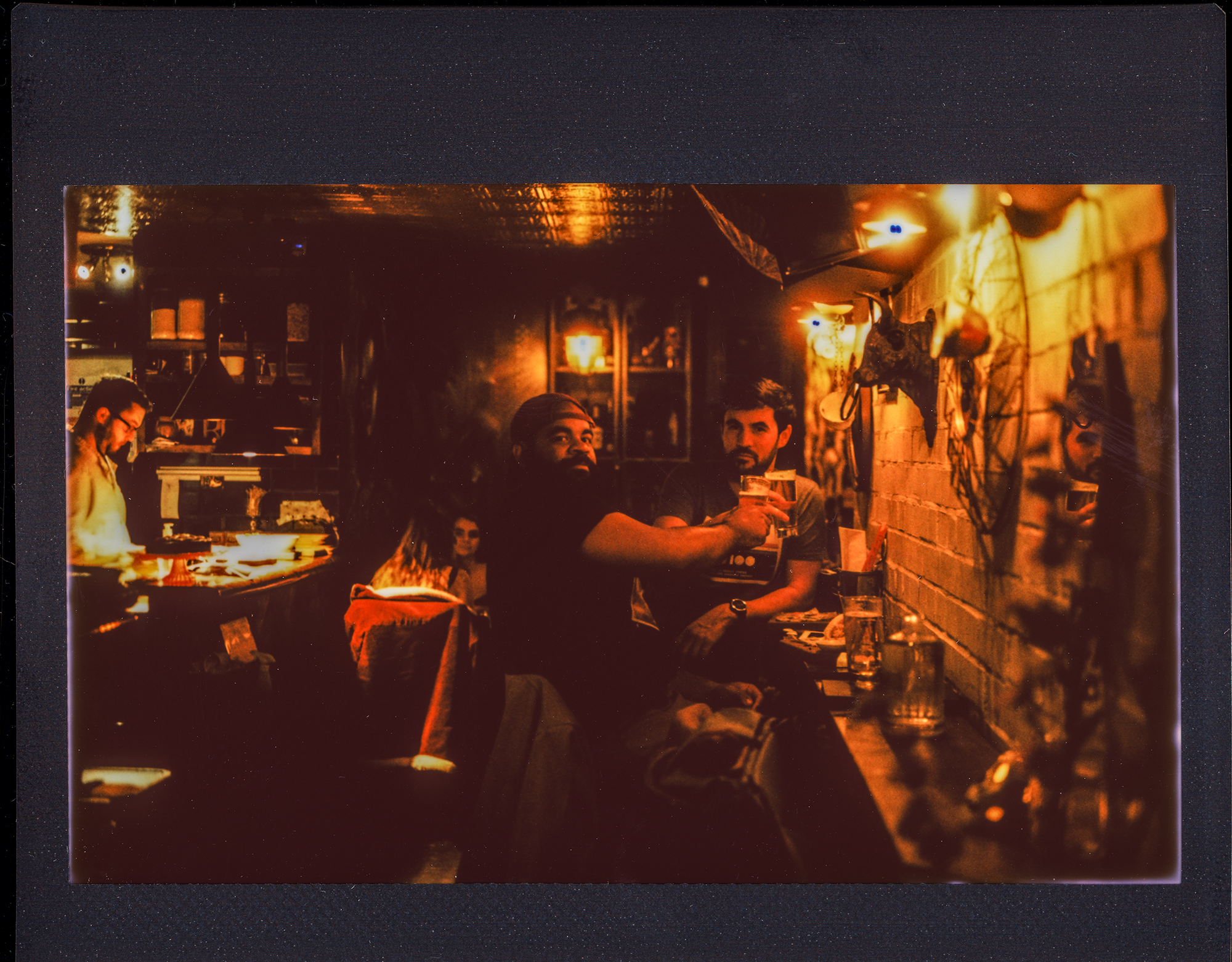
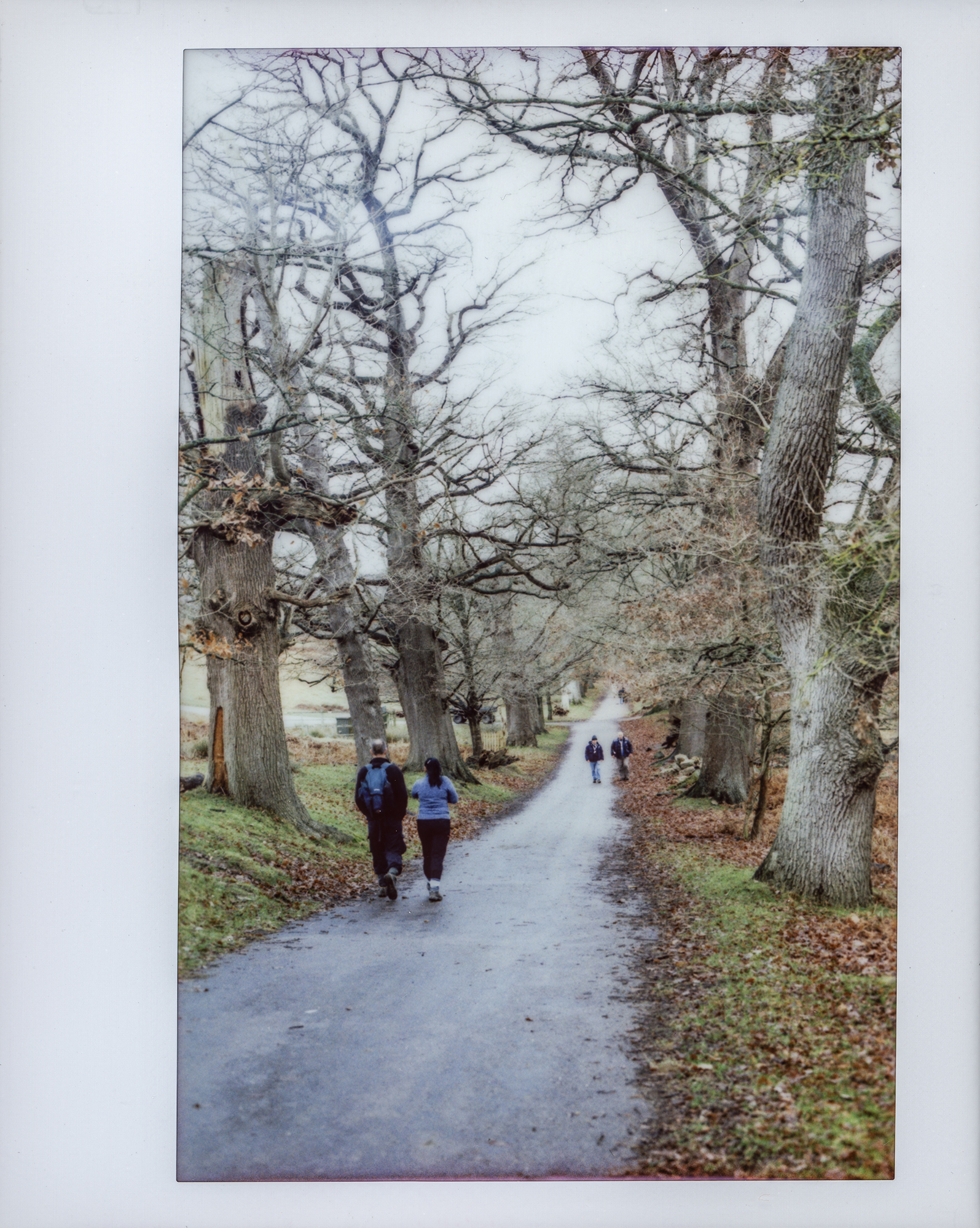
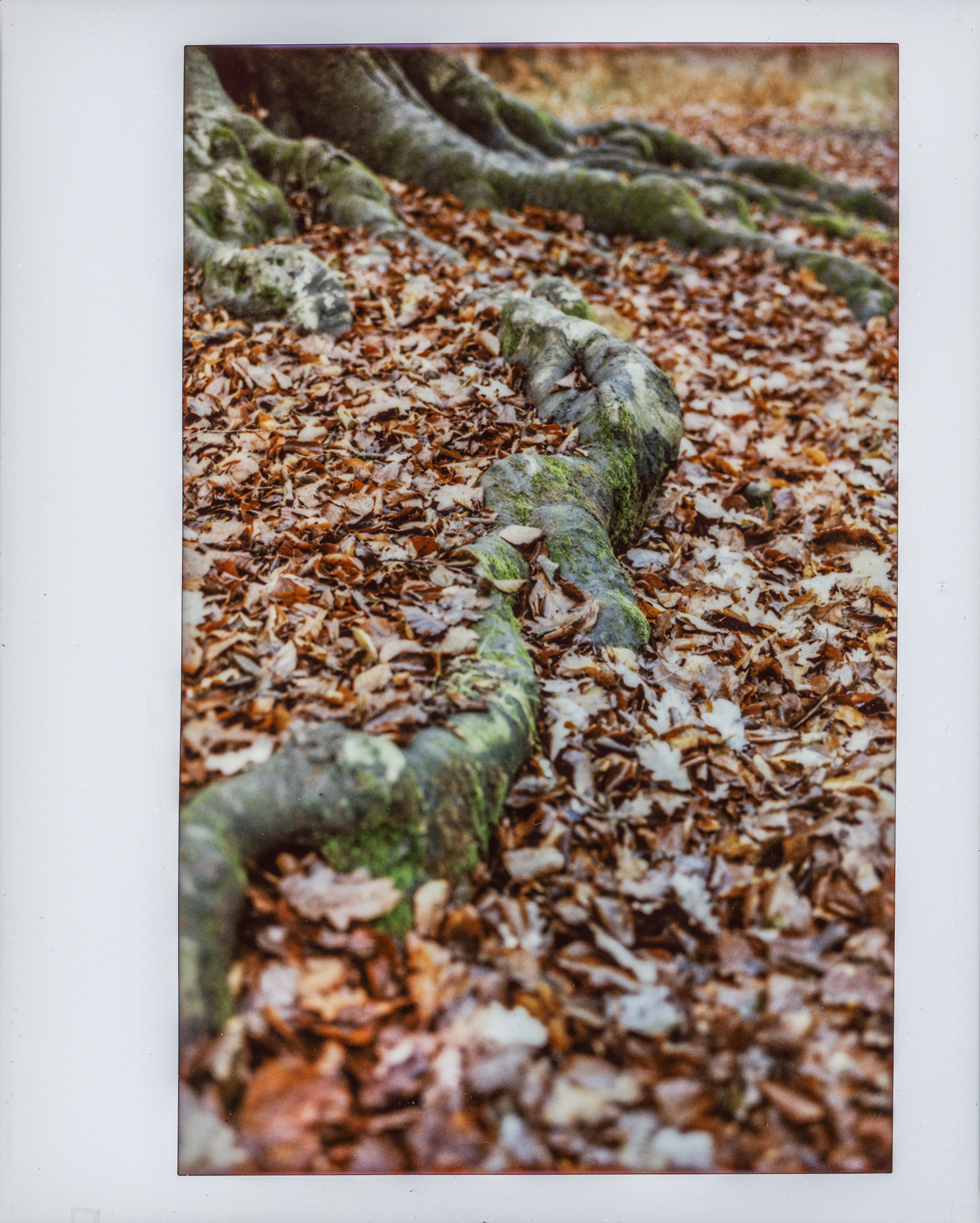
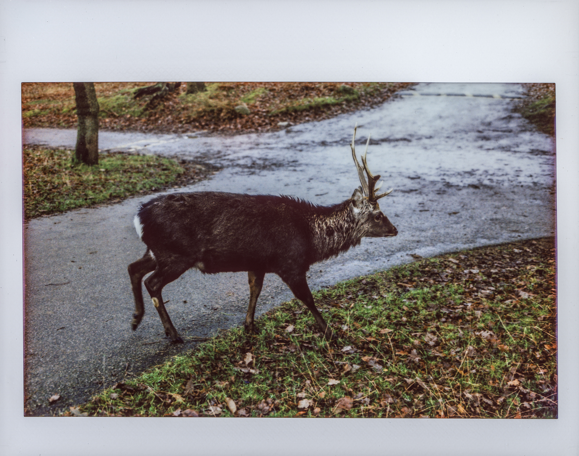
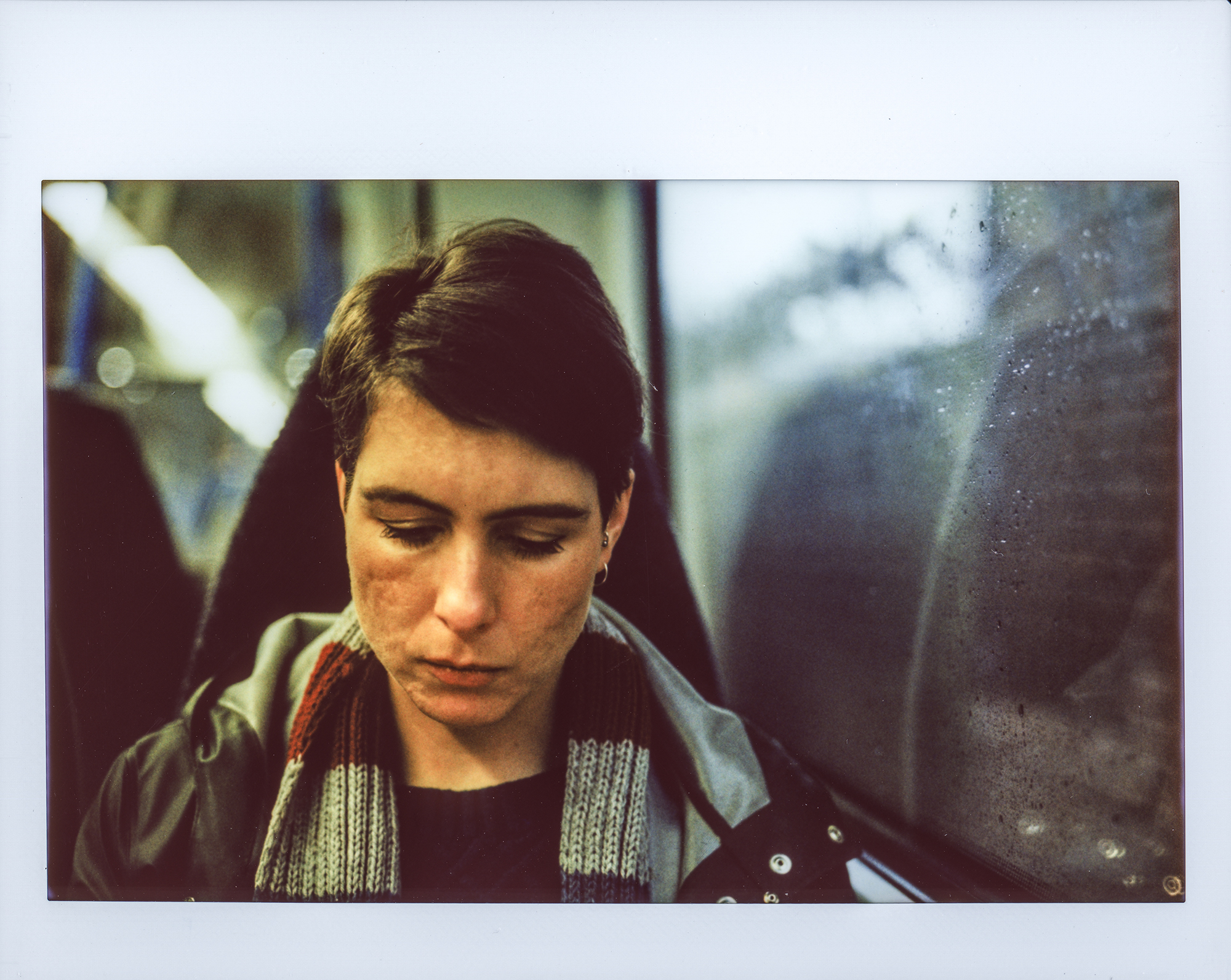
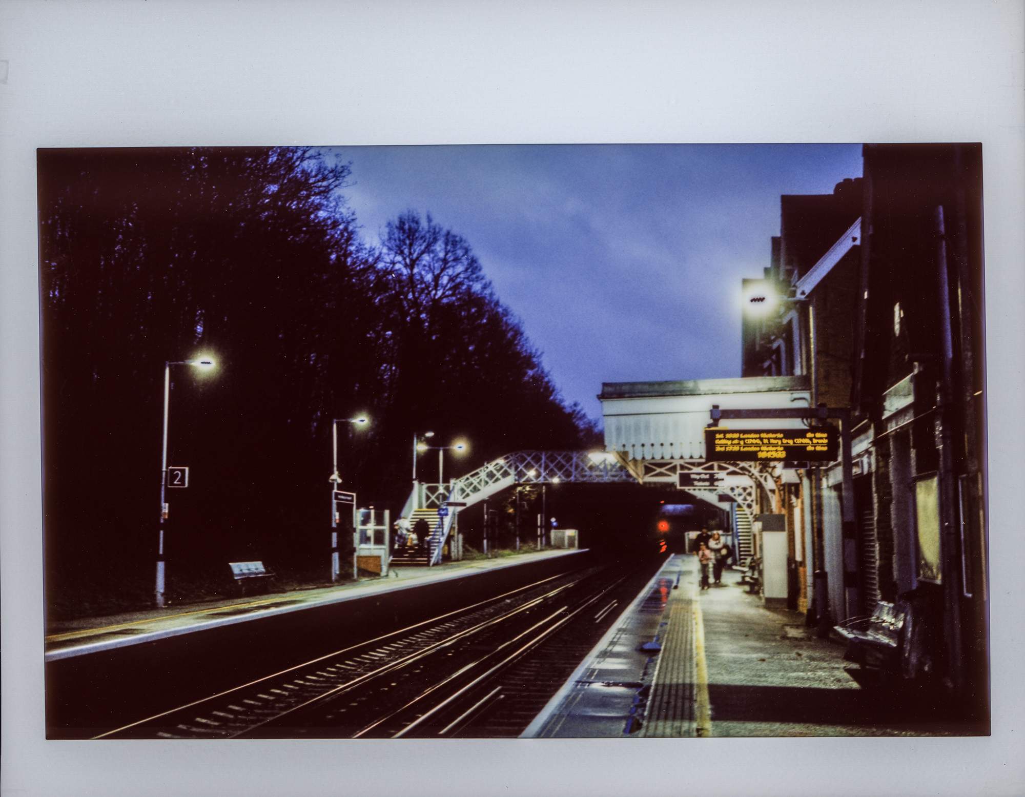
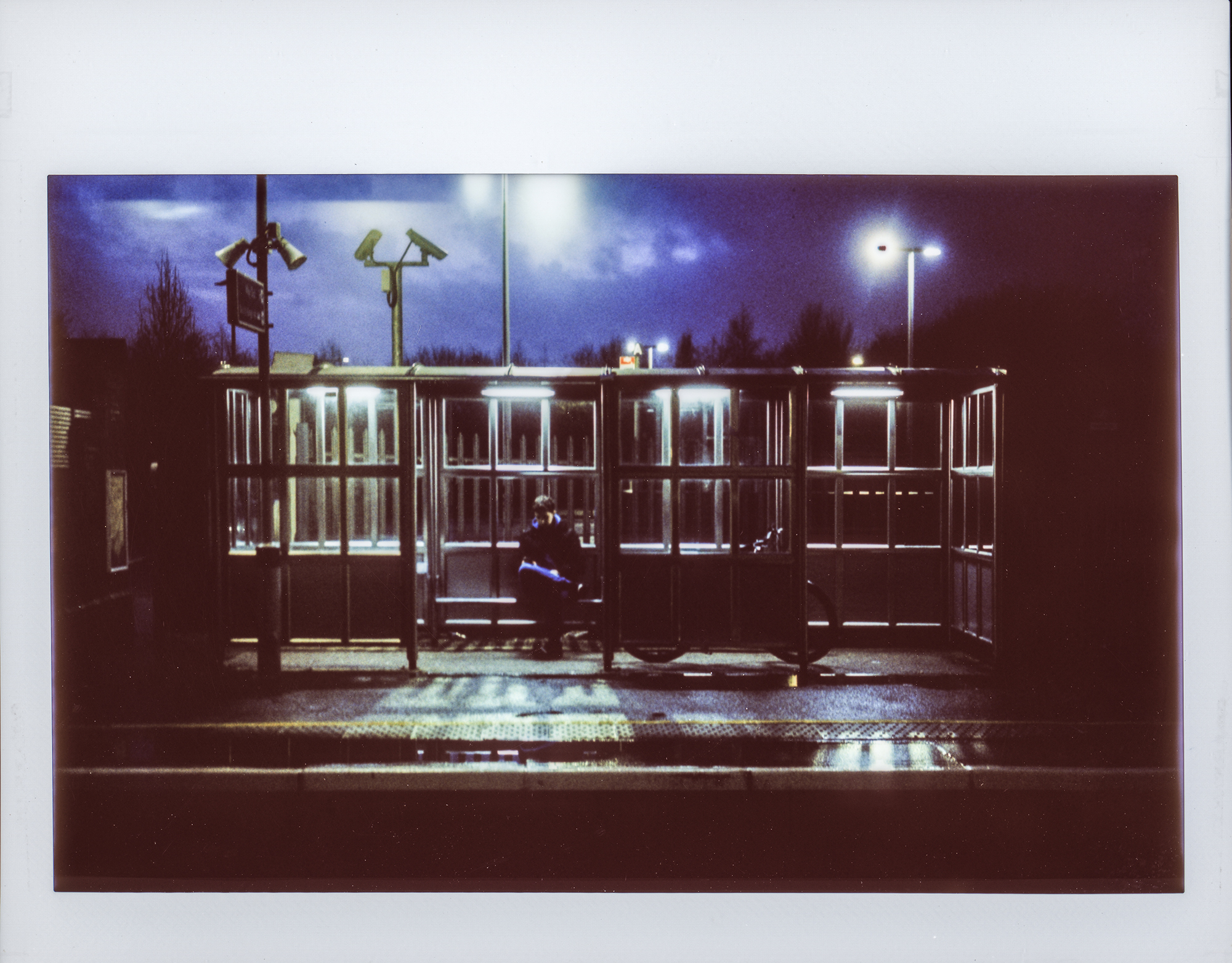
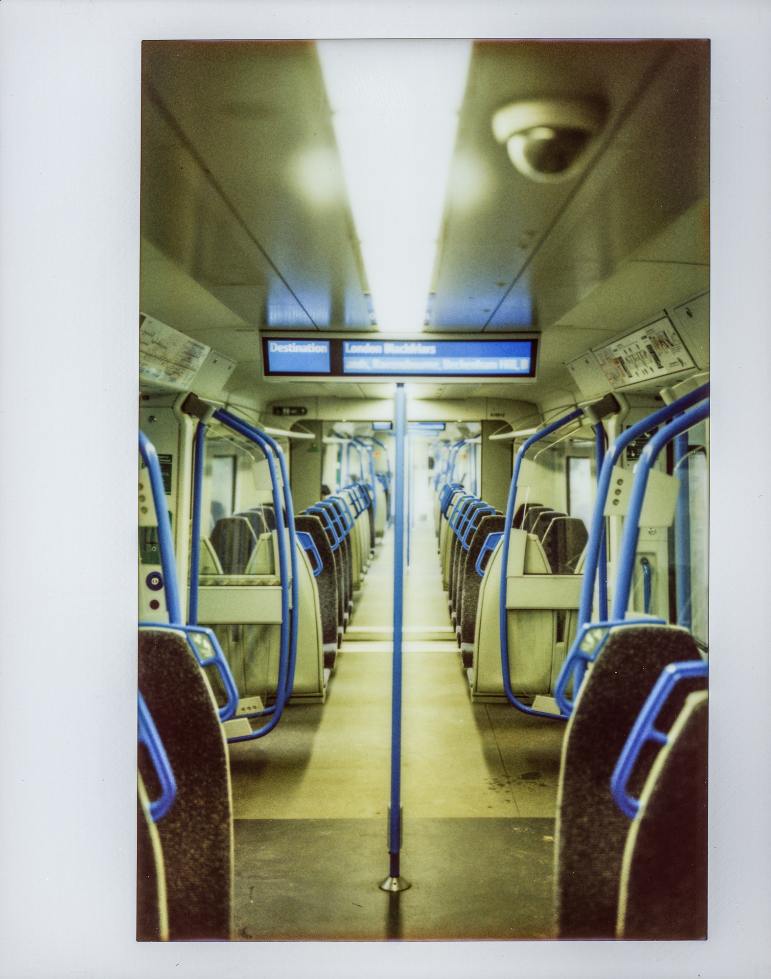
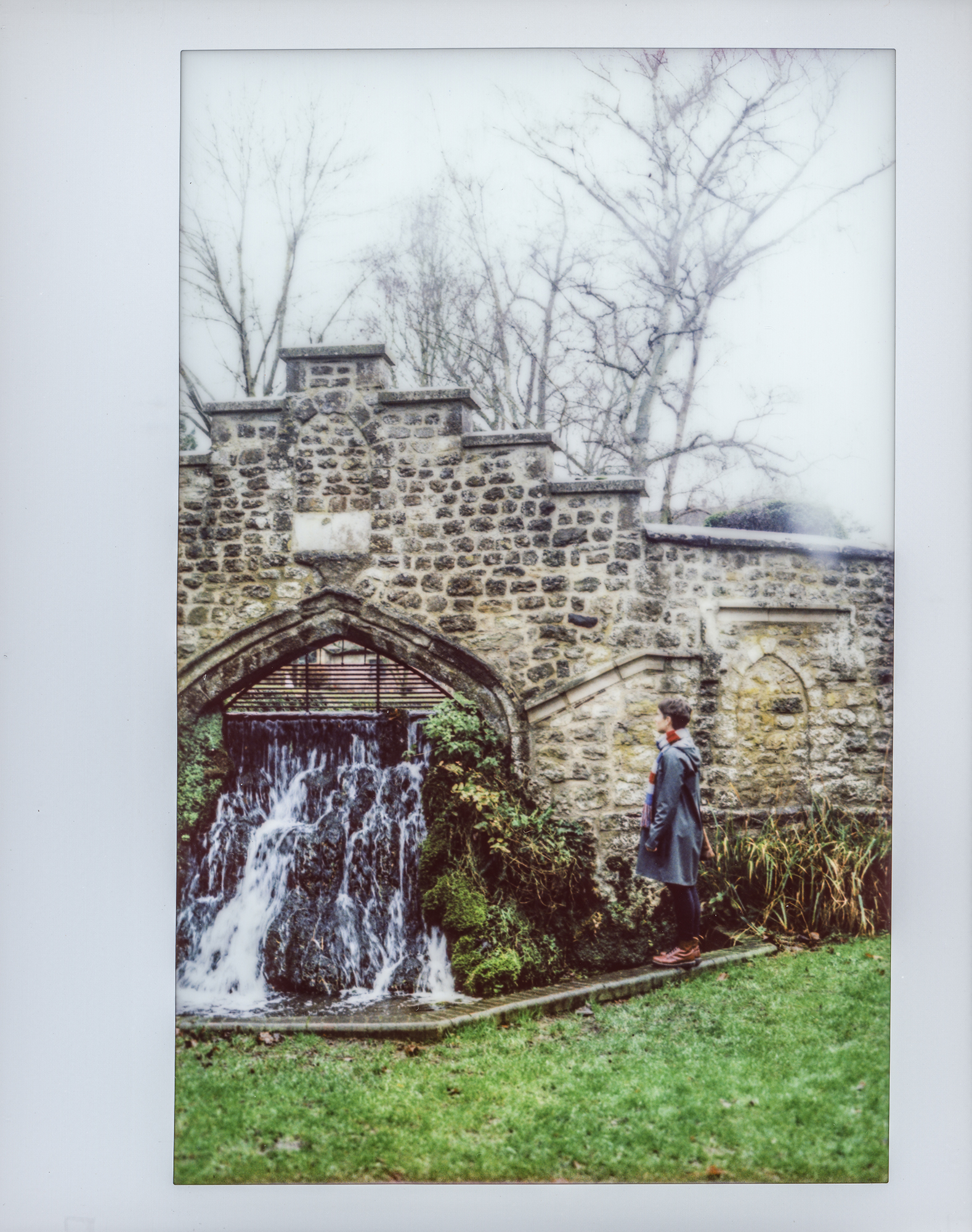
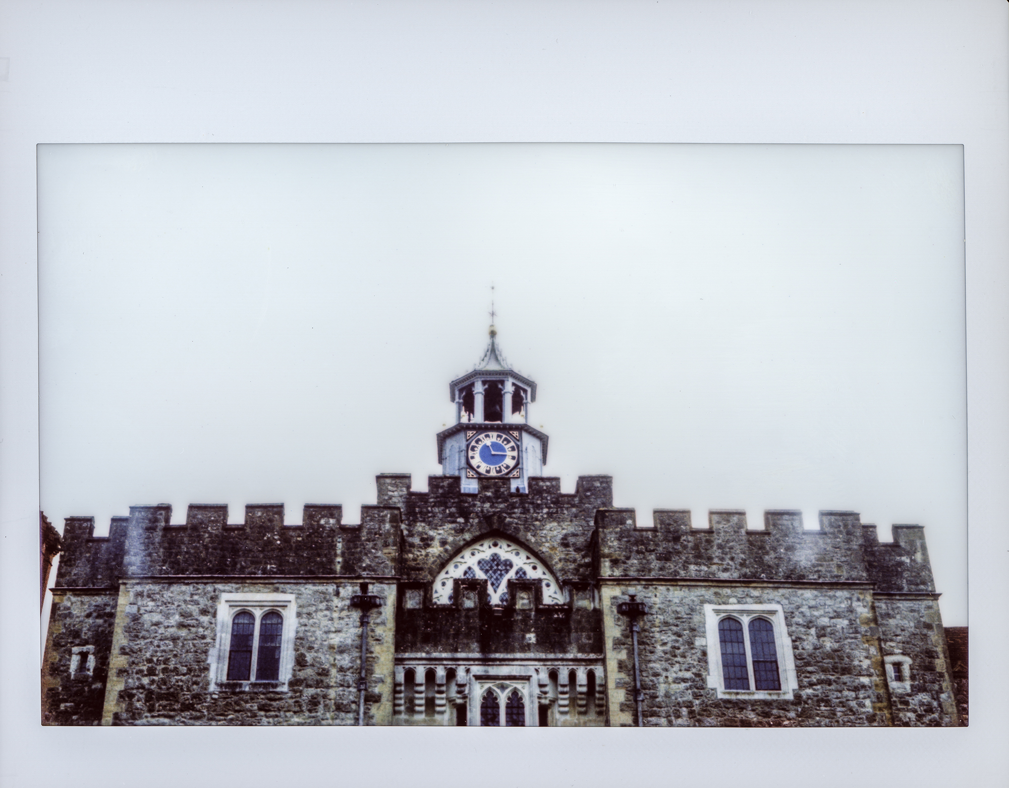
Here are a few sample photos…

A final note on the Lomograflok darkslide: If you’re not using the left grip, then you can still use the darkslide. I’ve bent mine slightly upwards at around a 30 degree angle at the handle, and this allows me to continue using it even with the Lomograflok mounted on the 110b. Still a bit of effort to get it out, though, so I’ve decided to leave it out and use the grip.
Conclusion
I really hope you enjoy shooting your newly converted camera as much as I do. It’s a real head-turner and conversation starter, and the perfect way to disarm subjects for very natural portraits. Even though the conversion is straightforward, it took a lot of effort to get here. The infinity stop went through about 12 iterations, and the bracket through about 8 (all printed). At the end of the day, apart from really wanting a decent Instax wide camera, I did this to share it all for others to reproduce and improve on.
Ribsy did a great walkthrough of the bespoke 110a conversion I did for him.